Garden tools and jigs · Guide 117
How to Make a Repeatable Seed-Spacing Template
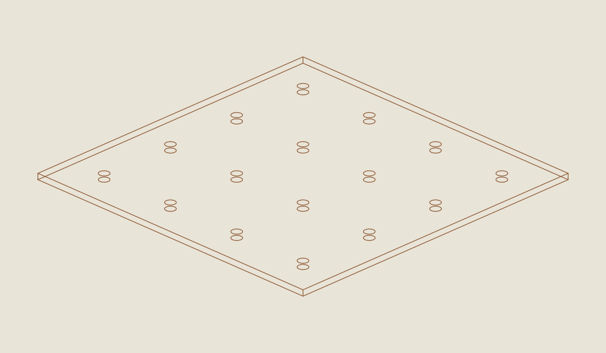
Make a 12-inch template with sixteen measured hole centers and edge registration that preserves the chosen spacing across consecutive placements.
01 / See the shape
View the project
Loading the 3D view…
Drag to turn. Pinch or use + / − to zoom. The written step covers workholding and tool use.
Scroll or swipe the enlarged drawing to read its dimensions. Choose Fit to see the whole drawing again.
Seed-spacing template. Check the dimensions and build steps before cutting.
02 / Plan your build
Before you start
The useful part of a spacing template is not the number of holes. It is that the last hole on one placement and the first hole on the next still have the intended spacing. This 12-inch board uses a 3-inch grid with 1-1/2-inch edge margins. Place another board-width along the same baseline and the spacing continues without a compressed or oversized gap at the join.
Use it only when 3-inch centers are appropriate to the planting task you have already chosen. A template does not decide crop spacing, sowing depth, thinning, mature plant size, or access between rows. Read the actual seed packet or crop guidance first. You can select every other row and column for a 6-inch layout, but that is a deliberate marking pattern, not a claim that either spacing suits every crop.
Where it goes
Use only on paper or prepared growing medium after choosing a crop-appropriate spacing. Do not drill, probe, or push sharp pegs into unknown ground.
Footprint: 12 × 12 inches.
What to expect
Beginner layout and clamped drilling with a sacrificial backing board. Plan 45–75 working minutes.
A planning estimate for the hands-on work, once the materials are bought and the tools are set up. It has not been timed on a finished build.
Check the spot
- Use only on paper or prepared growing medium after choosing a crop-appropriate spacing. Do not drill, probe, or push sharp pegs into unknown ground.
- Measure the boards and hardware you actually bought before you cut, and set up a steady work surface. Keep other people back while you cut and drill.
Stop and check first if…
- Confirm that the chosen planting task actually calls for 3-inch or deliberately selected 6-inch centers.
- Reject delaminated plywood, unknown chemical exposure, or torn test holes before drilling the real board.
- Do not use the board as a step, stool, ground probe, or load-bearing panel.
- The PDF plan is not a full-size tracing print: the 12-inch square does not fit on letter paper, and “fit to page” changes the scale. Drill from the written coordinates, or calibrate any large-format print first.
Work safely
- Use a tape or steel rule, square, pencil, clamps, supported saw, drill with a sharp 3/8-inch wood bit, sacrificial backing board, and abrasive paper. Eye protection and suitable dust and hearing controls are required for the actual operations. A drill can catch and rotate a small board; clamp it to the backing rather than holding its edge by hand.
- Choose a drill setup that can reach every hole while leaving enough supported board under the clamps. Do not put a clamp in the bit's path or reach underneath the work while drilling. Stop the tool before repositioning the template. No drilling takes place in the garden: the holes are made at the bench and the finished object is only a layout aid.
- Confirm that the chosen planting task actually calls for 3-inch or deliberately selected 6-inch centers.
- Reject delaminated plywood, unknown chemical exposure, or torn test holes before drilling the real board.
- Do not use the board as a step, stool, ground probe, or load-bearing panel.
- The PDF plan is not a full-size tracing print: the 12-inch square does not fit on letter paper, and “fit to page” changes the scale. Drill from the written coordinates, or calibrate any large-format print first.
Budget
We have not put a price on this one yet. Lumber and hardware prices change by store and season, so price the list under What you need at your local supplier before you buy.
03 / Gather and cut
What you need
Template panel
1 blank
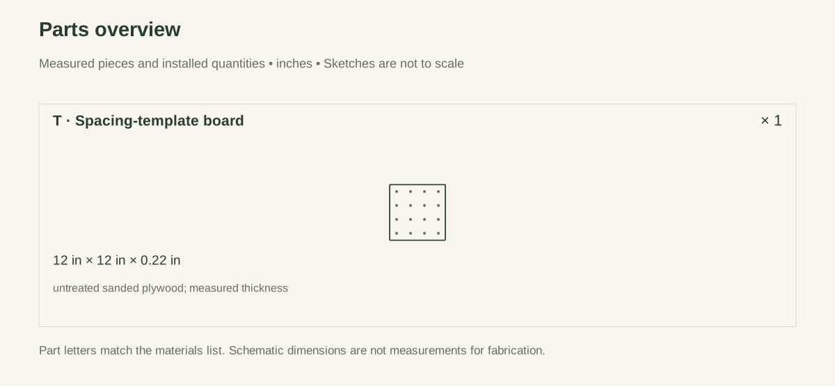
Flat untreated sanded plywood with actual reference thickness 0.220 inch. One blank yielding a true 12 × 12-inch square after trimming.
Hole centers on each axis: 1.5, 4.5, 7.5, and 10.5 inches. A nominal 24-inch panel may be 23.75 inches wide; do not assume it yields two exact 12-inch templates plus kerf.
Marking pen
1 pen
Durable pen for the datum edges, the 3-inch grid, and the “3-inch centers” label. One suitable pen.
No crop suitability is inferred from the grid.
Abrasive paper
As needed consumable
Fine abrasive for both faces and hole edges. Small sheet or pack.
Deburr without making wide funnel-shaped holes or losing the reference edges.
Optional marking tool
Optional tool
Blunt tool narrower than the 3/8-inch holes. Existing suitable hand tool; no attached pegs.
The template has no screws, dowels, glue, finish, handle, or sharp ground probes.
Cut list
| Piece | How many | Cut length | Note |
|---|---|---|---|
| T — Spacing-template board | 1 | 12 in | Part T, cut from untreated sanded plywood; measured thickness. Size: 12 × 12 × 0.22 in. Check the plan sheets for its reference edges and any shaped detail. |
Tools
- Rule, square, pencil, and durable labeling pen
- Clamps, stable bench, and sacrificial backing board
- Suitable saw for the supported plywood blank
- Drill with a suitable 3/8-inch wood bit
- Fine abrasive for both faces and hole edges
Protective gear
- Eye protection for cutting and drilling; match other protection to the actual tool instructions.
- Appropriate hearing protection and wood-dust control for the selected cutting method.
04 / Put it together
Build steps
- 01
Confirm the intended layout
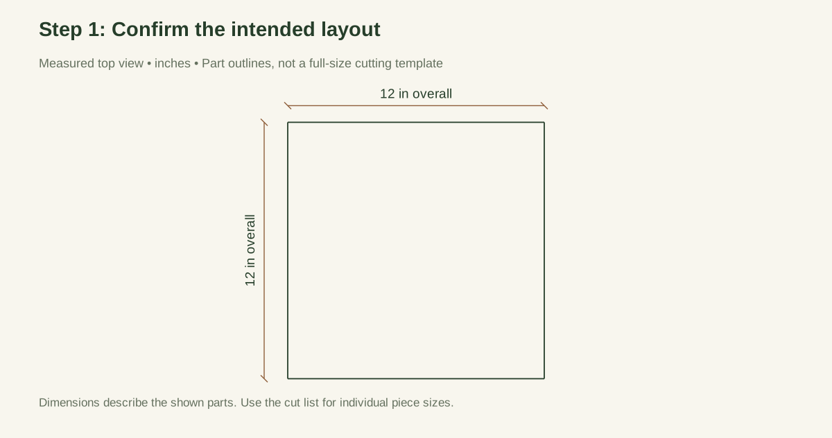
Write down the planting task and its required center spacing. Continue with the complete sixteen-hole pattern only for a task where 3-inch centers are appropriate. When the growing instructions require a different pattern, change the layout deliberately or use another method. Do not fill every hole simply because it exists.
Close-up · Whole model shows the complete part
Loading the 3D view…
Drag to turn. Pinch or use + / − to zoom. The written step covers workholding and tool use.
Scroll or swipe the enlarged drawing to read its dimensions. Choose Fit to see the whole drawing again.
Check: The chosen crop spacing is checked first; only compatible holes will be used.
- 02
Measure and inspect the panel
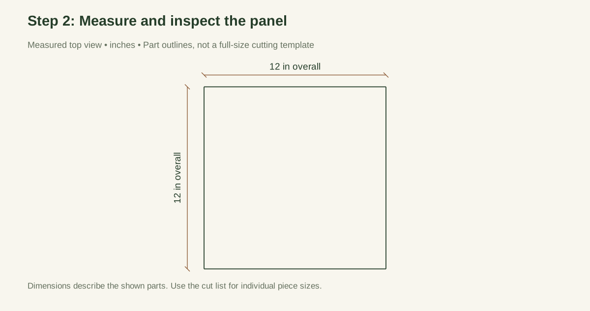
Measure actual thickness and check that the intended 12-inch square lies inside sound usable material. Look at the back as well as the face. Reject a bowed or separating panel; flattening it with your hand during layout would transfer inaccurate marks later. Mark a reference face and one datum corner.
Close-up · Whole model shows the complete part
Loading the 3D view…
Drag to turn. Pinch or use + / − to zoom. The written step covers workholding and tool use.
Scroll or swipe the enlarged drawing to read its dimensions. Choose Fit to see the whole drawing again.
Check: The entire 12-inch-square layout fits sound measured panel stock without a defect at a future hole.
- 03
Cut a true 12-inch square
Lay out the square from the same datum edges, allowing for the saw kerf on the waste side. Clamp and support the panel for the cut. After cutting, check both widths and all four corners. The ideal diagonal is 12 × √2 = 16.9706 inches. The proposed shop target is each side within 1/32 inch of 12 and a diagonal difference within 1/16 inch.
If the finished board is undersized or skewed, do not keep the same edge-registration instructions and call it a 12-inch repeat. Correct or remake it before drilling the pattern.
Close-up · Whole model shows the complete part
Loading the 3D view…
Drag to turn. Pinch or use + / − to zoom. The written step covers workholding and tool use.
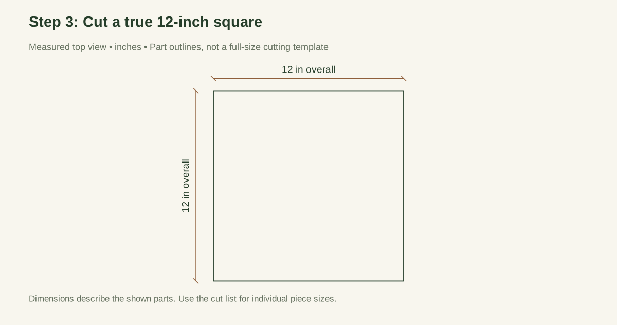
Scroll or swipe the enlarged drawing to read its dimensions. Choose Fit to see the whole drawing again.
Check: The finished panel is 12 × 12 inches with square edges; do not use the repeat method on an undersized blank.
- 04
Mark the four x coordinates from one edge
On the reference face, measure 1-1/2, 4-1/2, 7-1/2, and 10-1/2 inches from the left datum edge. Use a square to extend light lines across the face. Make every measurement from that edge; do not step the ruler along four times and accumulate error.
Close-up · Whole model shows the complete part
Loading the 3D view…
Drag to turn. Pinch or use + / − to zoom. The written step covers workholding and tool use.
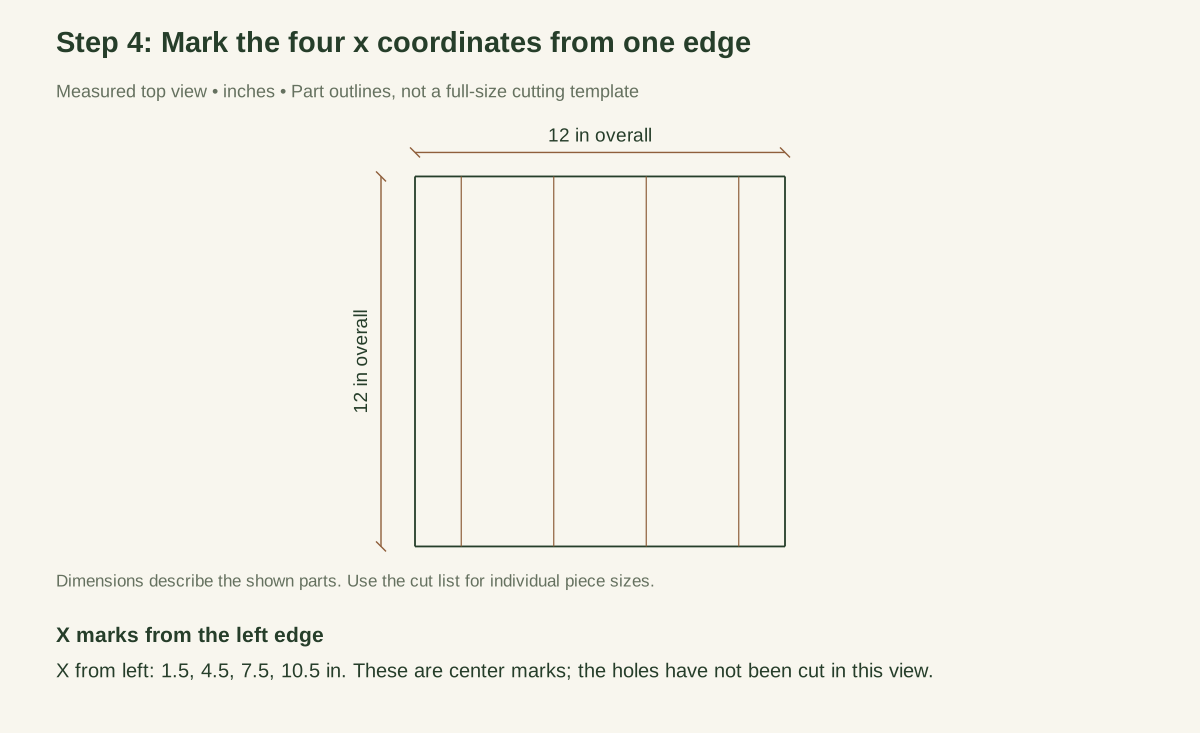
Scroll or swipe the enlarged drawing to read its dimensions. Choose Fit to see the whole drawing again.
Measure all X positions from the left datum; do not step the ruler from hole to hole.
Check: Four x positions are measured from one edge: 1.5, 4.5, 7.5 and 10.5 inches.
- 05
Mark the same four y coordinates
Measure the same four positions from the bottom datum edge and square lines across them. The sixteen intersections are the drill centers. Mark a small cross at each intersection. Do not eyeball a center from a wide pencil dot. Check that the outer rows and columns are 1-1/2 inches from their nearest board edges.
Close-up · Whole model shows the complete part
Loading the 3D view…
Drag to turn. Pinch or use + / − to zoom. The written step covers workholding and tool use.
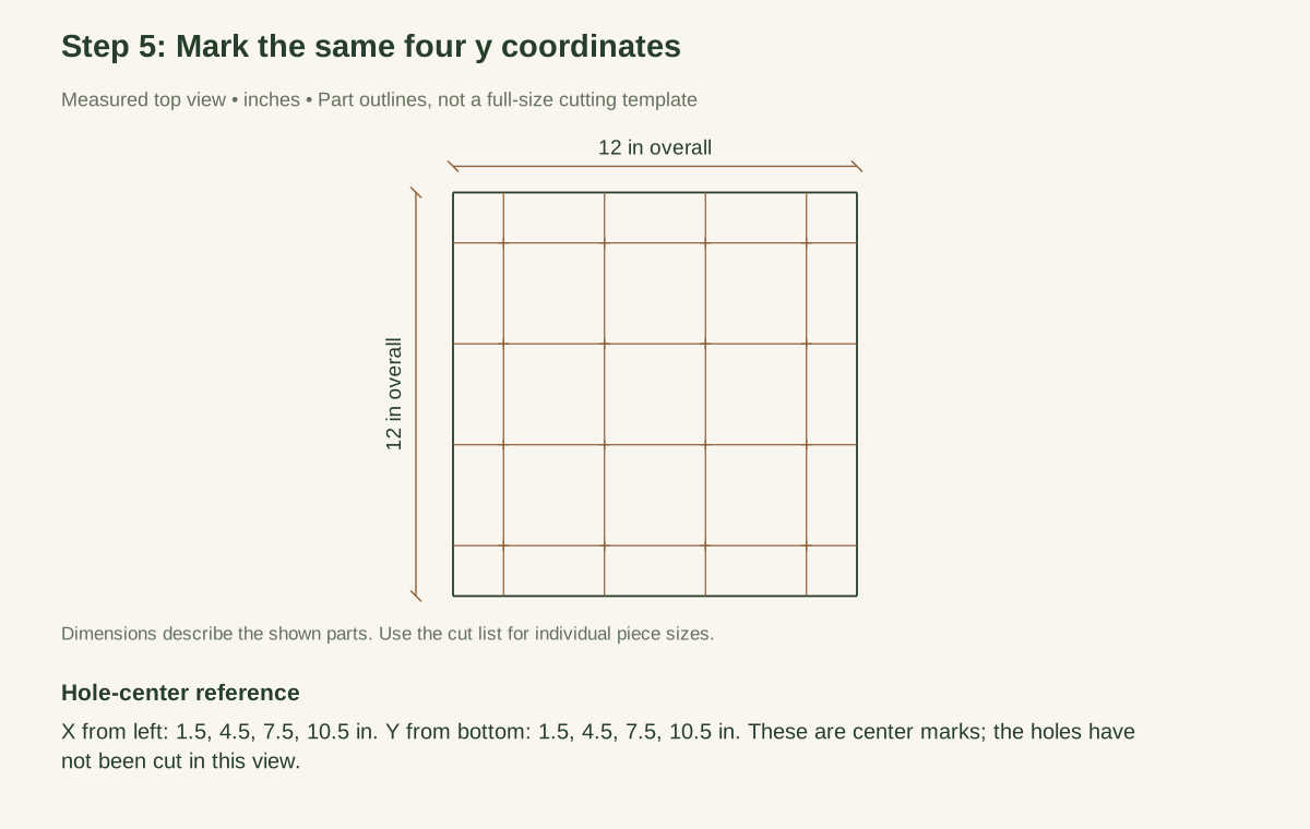
Scroll or swipe the enlarged drawing to read its dimensions. Choose Fit to see the whole drawing again.
Measure Y from the same bottom edge used by the drawing.
Check: Four y positions use the same sequence from the perpendicular datum; outer margins are 1.5 inches.
- 06
Verify the coordinates before making a hole
Measure between neighboring centers in both directions: each should be 3 inches. Check the diagonal between opposite pattern corners: 9 × √2 = 12.7279 inches. The hole pattern should be centered, leaving equal margins. Check this marked state carefully; a finished board can hide a layout error.
The full coordinate set is every pairing of the four x values with the four y values. There are 4 × 4 = 16 holes, not four corner holes plus an improvised middle pattern. All hole centers must follow those same coordinates.
Close-up · Whole model shows the complete part
Loading the 3D view…
Drag to turn. Pinch or use + / − to zoom. The written step covers workholding and tool use.
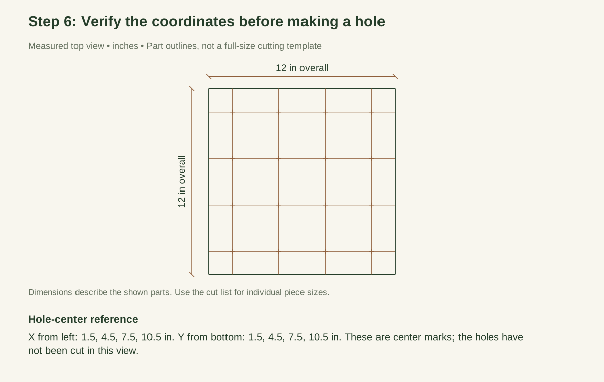
Scroll or swipe the enlarged drawing to read its dimensions. Choose Fit to see the whole drawing again.
Check: All sixteen intersections are checked before drilling, with 3-inch adjacent spacing and equal margins.
- 07
Drill a test hole in an offcut
Clamp an offcut of the selected plywood against the backing. Drill one 3/8-inch hole using the bit and tool instructions. Inspect both faces for breakout or tearing. Adjust backing, bit condition, and feed before working on the real board. A torn test hole is a reason to correct the setup, not to increase pressure.
Close-up · Whole model shows the complete part
Loading the 3D view…
Drag to turn. Pinch or use + / − to zoom. The written step covers workholding and tool use.
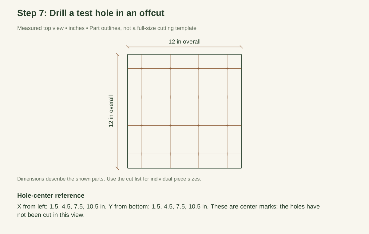
Scroll or swipe the enlarged drawing to read its dimensions. Choose Fit to see the whole drawing again.
The center pattern is a reference. Test the drill in a separate offcut first.
Check: A trial 3/8-inch hole has clean front/back faces and does not split the actual panel.
- 08
Drill the sixteen holes with the board clamped
Support the board flat on sacrificial backing and clamp it securely. Drill perpendicular to the face, clearing chips only with the tool stopped. Reposition clamps when required rather than holding the next corner by hand. Keep the drill out of the metal clamps. Count completed holes against the coordinate schedule so a missed or duplicated position is caught immediately.
Close-up · Whole model shows the complete part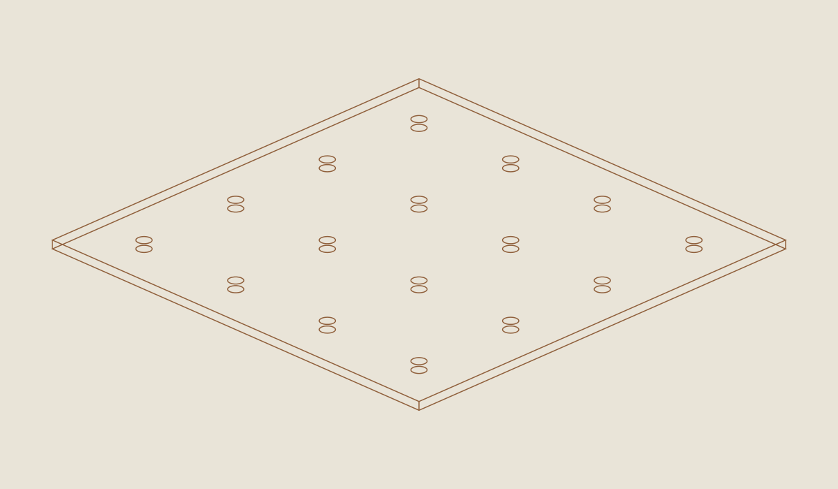
Loading the 3D view…
Drag to turn. Pinch or use + / − to zoom. The written step covers workholding and tool use.
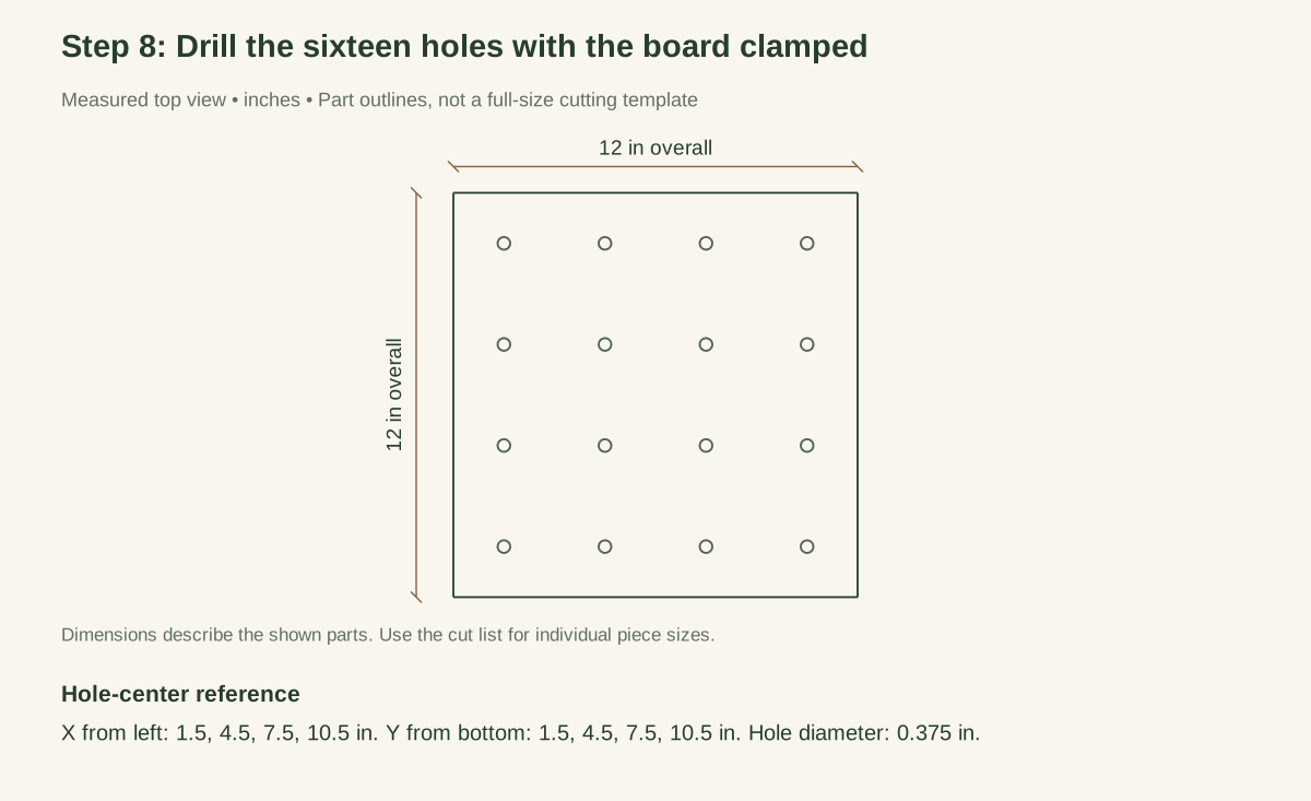
Scroll or swipe the enlarged drawing to read its dimensions. Choose Fit to see the whole drawing again.
Check: All sixteen 3/8-inch holes are drilled with clamped backing; no loose panel is held in the hand.
- 09
Deburr without moving the centers
Remove splinters on both faces and lightly ease the hole edges. Do not create a large funnel-shaped countersink: the working opening should remain close to 3/8 inch and the marked center should stay meaningful. Smooth the outside perimeter without rounding the datum edges so much that registration becomes uncertain.
The theoretical wood remaining between the nearest hole edge and board edge is 1.5 − 0.1875 = 1.3125 inches. This is a geometric margin, not a load-bearing calculation. The board is not for standing, kneeling, or supporting a container.
Close-up · Whole model shows the complete part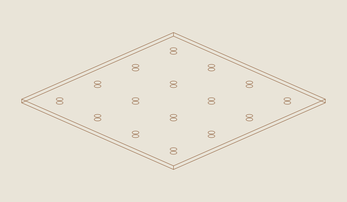
Loading the 3D view…
Drag to turn. Pinch or use + / − to zoom. The written step covers workholding and tool use.
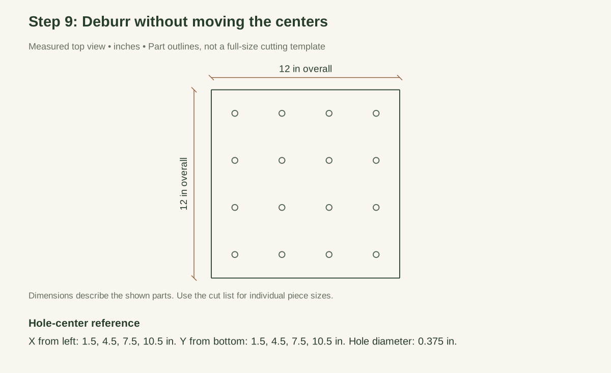
Scroll or swipe the enlarged drawing to read its dimensions. Choose Fit to see the whole drawing again.
Check: Burrs are removed without enlarging openings into funnels or moving their useful centers.
- 10
Label the spacing and datum
Mark “3-inch centers” and an arrow to the datum corner. Add small row/column identifiers on the face where they will not hide the centers. A second-color mark can identify the four holes at x/y combinations 1-1/2 and 7-1/2 inches for a deliberately selected 6-inch pattern. Keep that option visibly separate from the full grid.
Close-up · Whole model shows the complete part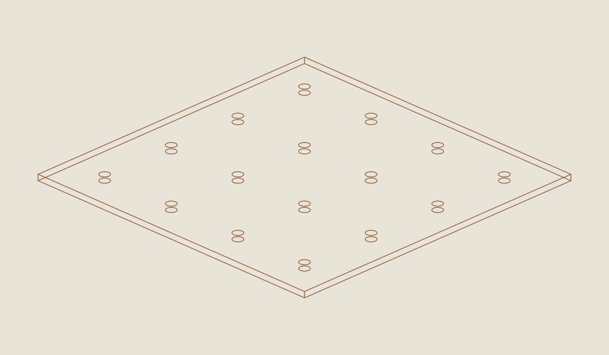
Loading the 3D view…
Drag to turn. Pinch or use + / − to zoom. The written step covers workholding and tool use.
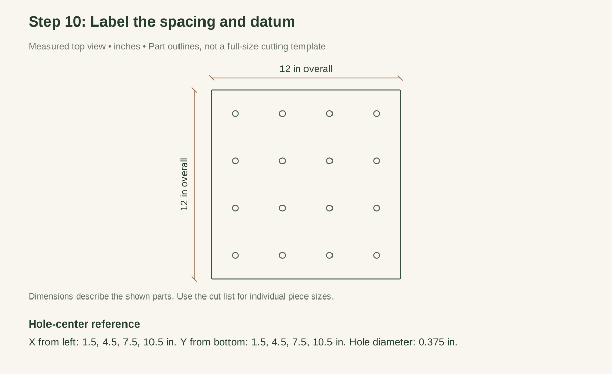
Scroll or swipe the enlarged drawing to read its dimensions. Choose Fit to see the whole drawing again.
Check: The board is labeled 3-inch centers and a datum arrow; any skipped-hole option is clearly separate.
- 11
Test on paper before using it near seedlings
Set the template on a clean sheet and make a small mark through every selected hole with a blunt tool. Remove the board and measure the marks. Then register a second placement exactly one 12-inch board-width along the baseline and mark again. A final first-board center at 10-1/2 followed by a second-board center at 13-1/2 gives the intended 3-inch seam spacing.
For the selected 6-inch pattern, centers at 1-1/2 and 7-1/2 continue at 13-1/2 on the next placement. The first margin remains 1-1/2, not a newly invented 3-inch crop setback. Choose the starting location deliberately for the actual bed boundaries.
Close-up · Whole model shows the complete part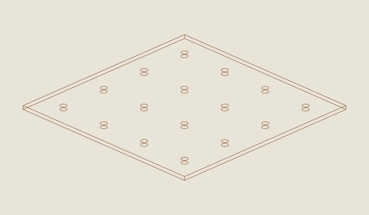
Loading the 3D view…
Drag to turn. Pinch or use + / − to zoom. The written step covers workholding and tool use.
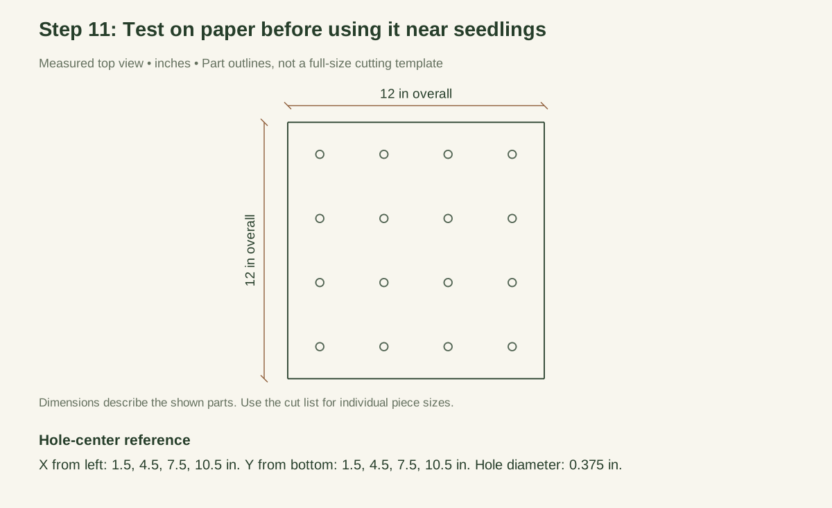
Scroll or swipe the enlarged drawing to read its dimensions. Choose Fit to see the whole drawing again.
Transfer the pattern to paper and measure the result before working near seedlings.
Check: A paper test confirms 3-inch spacing across both the board and the seam between consecutive placements.
- 12
Trial it on prepared growing medium
Use only an already prepared, known growing surface. Place the board gently without pressing it into the soil or resting it on plants. Make shallow position marks through the chosen holes; the marking tool is not a depth gauge and must not be used to probe unknown ground. Lift the board vertically to avoid smearing the marks. Sow or transplant afterward using the actual crop instructions.
Close-up · Whole model shows the complete part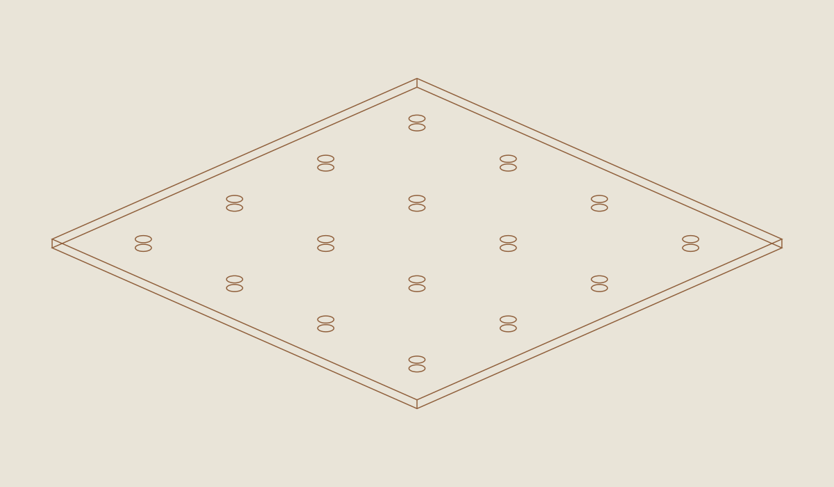
Loading the 3D view…
Drag to turn. Pinch or use + / − to zoom. The written step covers workholding and tool use.
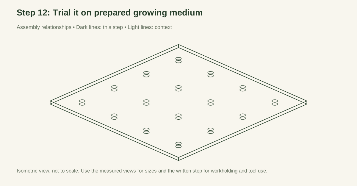
Scroll or swipe the enlarged drawing to read its dimensions. Choose Fit to see the whole drawing again.
Check: Use only for shallow position marks in prepared media; the marking tool is not a depth or utility probe.
05 / Keep it sound
Care
After the build
- Verify the 3-inch grid against the actual crop instructions before using the template.
- Test two adjacent placements on paper: the boundary gap must also be 3 inches when the board advances by 12 inches.
Check it each season
- Brush off soil while it is loose, wipe only as needed, and dry the board flat with air on both faces. Store it indoors, away from damp seed trays. Do not soak the plywood or leave it on wet ground overnight. Before each use, check for warping, splinters, worn hole edges, and legible spacing marks. Recommended checks are use-based; no tested service life has been assigned.
- Use the seed organizer to keep the relevant packet with its layout notes. The string winder can help store a short reference line, but a line crossing a walkway is not an acceptable permanent layout aid.
If something looks wrong
- Spacing changes at the join
- Check: Finished board size, registration, selected pattern. Fix: Recheck on paper; correct the repeat distance or remake an undersized board.
- Marks are scattered
- Check: Oversized/worn holes or a loose marking tool. Fix: Use a controlled small mark; replace a badly worn template.
- Board rocks on a flat bench
- Check: Warped panel. Fix: Replace it; hand pressure does not restore reliable geometry.
- Hole edges splinter
- Check: Drill breakout or repeated wetting. Fix: Remove from use until smooth, or replace the board.
- Crop becomes crowded
- Check: Wrong agronomic spacing choice. Fix: Follow the crop's thinning/transplant guidance; more precise marks do not make a wrong spacing appropriate.
Keep exploring