Compost projects · Guide 68
How to Build a Soil-Mixing Tray with a Removable Liner
Build a supported 22 × 16-inch garden-mixing tray with a replaceable floor liner and folded, unslit corners.
01 / See the shape
View the project
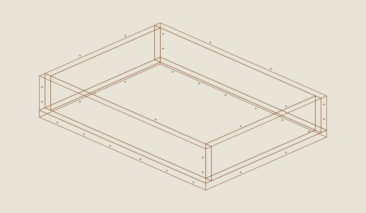
Loading the 3D view…
Drag to turn. Pinch or use + / − to zoom. The written step covers workholding and tool use.
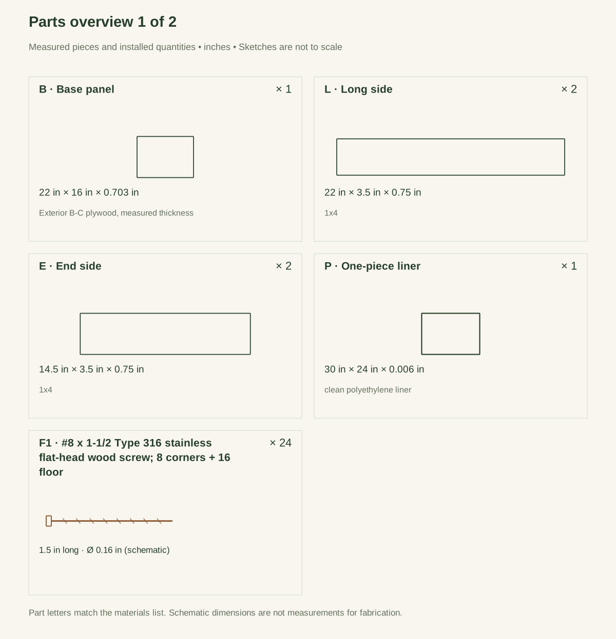
Scroll or swipe the enlarged drawing to read its dimensions. Choose Fit to see the whole drawing again.
Lined soil-mixing tray. Check the dimensions and build steps before cutting.
02 / Plan your build
Before you start
A small mixing tray keeps a scoop of potting medium on the work surface instead of on the patio. The useful detail is not a decorative finish: it is the removable liner. Lift that out after emptying, brush the corners, and let both the liner and wood dry separately.
This tray has a plywood floor, four low wooden sides, and a one-piece folded polyethylene liner held with removable clips. It is intended for small batches of damp growing medium on a fully supporting surface. It is not a water tank, mortar pan, pesticide-mixing vessel, food tray, seedling bed, or carrying box. Keep it empty while moving it. A liner does not turn plywood into a permanently waterproof container.
Where it goes
Support the entire base on a stable, level, moisture-tolerant surface. Do not bridge sawhorses, support corners only, or lift a filled batch by the rim.
Footprint: 22 × 16 inches. The whole base needs to rest on a flat, solid surface.
What to expect
Beginner rectangular joinery with careful floor-screw direction and liner fitting. Plan 2–3 working hours.
A planning estimate for the hands-on work, once the materials are bought and the tools are set up. It has not been timed on a finished build.
Check the spot
- Support the entire base on a stable, level, moisture-tolerant surface. Do not bridge sawhorses, support corners only, or lift a filled batch by the rim.
- Measure the boards and hardware you actually bought before you cut, and set up a steady work surface. Keep other people back while you cut and drill.
Stop and check first if…
- Stop for an unknown panel bond classification, changed actual thickness, damaged liner, or a clip that punctures the sheet.
- Do not use for potable water, food contact, or liquid storage, and do not reuse a sheet that held paint, fuel, or pesticide.
- Keep the proposed working depth at or below 2 inches; that is not a tested weight rating.
Work safely
- Prepare a rule, square, pencil, clamps, supported saw, drill/driver, countersink, appropriate pilot/clearance bits, scissors for the liner, and abrasive paper. Use eye protection, hearing protection where appropriate, and dust extraction or suitable respiratory protection for the actual cutting task. Clamp panels and narrow sides; do not reach underneath a panel into the saw path.
- Read the growing-medium bag's handling instructions before opening it. Work where dust and spilled material can be controlled, wash hands afterward, and keep the tray separate from kitchen equipment. There is no ground disturbance or utility work in this project. A bench modification, electrical tool station, or plumbing connection is outside the plan.
- Stop for an unknown panel bond classification, changed actual thickness, damaged liner, or a clip that punctures the sheet.
- Do not use for potable water, food contact, or liquid storage, and do not reuse a sheet that held paint, fuel, or pesticide.
- Keep the proposed working depth at or below 2 inches; that is not a tested weight rating.
Budget
We have not put a price on this one yet. Lumber and hardware prices change by store and season, so price the list under What you need at your local supplier before you buy.
03 / Gather and cut
What you need
Plywood base
1 panel
Sound B-C plywood with verified Exterior bond classification; reference thickness 0.703 inch. A panel blank yielding 22 × 16 inches after trimming.
Check the grade stamp and actual thickness. Exposure 1 is not the specified bond classification; a retailer's nominal size is not a measured blank.
Pine side boards
1 board
Untreated sound 1 × 4; actual 0.75 × 3.5 inches. One 8-foot board.
Two 22-inch long walls and two 14.5-inch ends use 73 inches plus kerf and trimming. Long walls run through the corners.
Removable liner
1 sheet
Known-clean 6-mil polyethylene sheet for garden-material use only. One 30 × 24-inch sheet.
Fold the corners without slitting them. No chemical-container reuse, permanent fastener, drain, caulk, or food-contact claim.
Wood screws
24 screws
#8 × 1.5-inch Type 316 stainless flat-head wood screws. Package containing at least 24.
Eight corner screws and sixteen floor screws. Follow the distinct underside positions in the build steps.
Padded rim clips
8 clips
Removable spring clips fitted to the actual 0.75-inch wall and liner. Eight clips, two per side.
Must hold without piercing the liner or dropping into the batch; the liner rests on the floor, not suspended by clips.
Cut list
| Piece | How many | Cut length | Note |
|---|---|---|---|
| B — Base panel | 1 | 22 in | Part B, cut from Exterior B-C plywood, measured thickness. Size: 22 × 16 × 0.703 in. Check the plan sheets for its reference edges and any shaped detail. |
| L — Long side | 2 | 22 in | Part L, cut from 1x4. Size: 22 × 3.5 × 0.75 in. Check the plan sheets for its reference edges and any shaped detail. |
| E — End side | 2 | 14.5 in | Part E, cut from 1x4. Size: 14.5 × 3.5 × 0.75 in. Check the plan sheets for its reference edges and any shaped detail. |
| P — One-piece liner | 1 | 30 in | Part P, cut from clean polyethylene liner. Size: 30 × 24 × 0.006 in. Check the plan sheets for its reference edges and any shaped detail. |
Tools
- Tape or rule, square, and pencil
- Clamps and stable supported work surface
- Suitable saw with its required guarding
- Drill/driver, selected-product pilot and clearance bits, and countersink
- Abrasives for hand-contact edges
- Non-sharp folding and marking aids for the liner
- Scissors appropriate to the clean polyethylene sheet
Protective gear
- Eye protection for cutting and drilling; match other protection to the actual tool instructions.
- Appropriate hearing protection and wood-dust control for the selected cutting method.
04 / Put it together
Build steps
- 01
Record the floor thickness
Measure the actual panel, note its grade stamp, and recalculate the overall height and floor fastening detail when it differs from the 0.703-inch reference. The footprint and side cut lengths stay the same; the overall height changes. Check that the proposed 1-1/2-inch floor screws will remain fully contained in the 3-1/2-inch-high side boards after passing through the measured floor. Do not simply round thickness up to 3/4 for the drawings.
Close-up · Whole model shows the complete part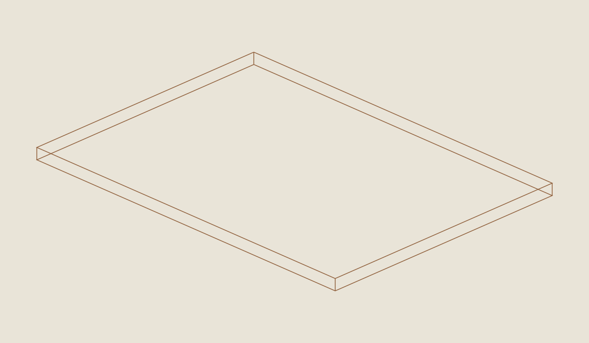
Loading the 3D view…
Drag to turn. Pinch or use + / − to zoom. The written step covers workholding and tool use.
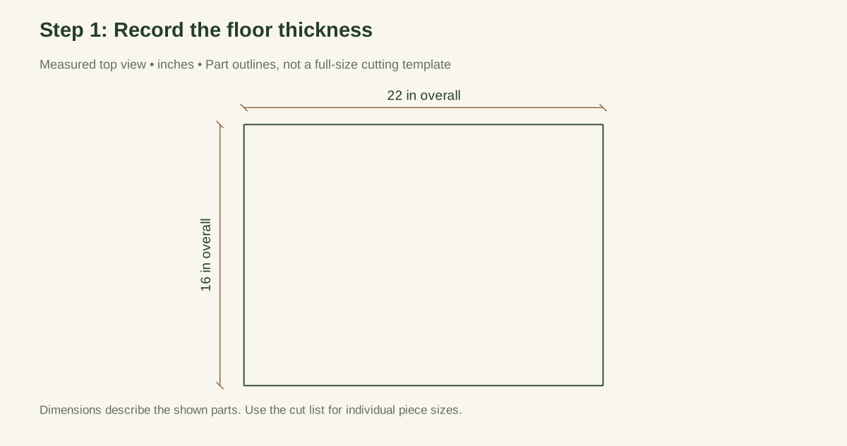
Scroll or swipe the enlarged drawing to read its dimensions. Choose Fit to see the whole drawing again.
Check: The actual plywood thickness and grade are recorded; recalculate overall height when they differ from the reference.
- 02
Cut the base and four sides
Cut B to 22 × 16, two L pieces to 22, and two E pieces to 14-1/2. Use square, finished ends. Label the lower edge of each side; all corner-hole heights refer to that edge. Ease sharp exposed edges, but leave the underside seating faces flat. Remove splinters that could puncture the liner.
Close-up · Whole model shows the complete part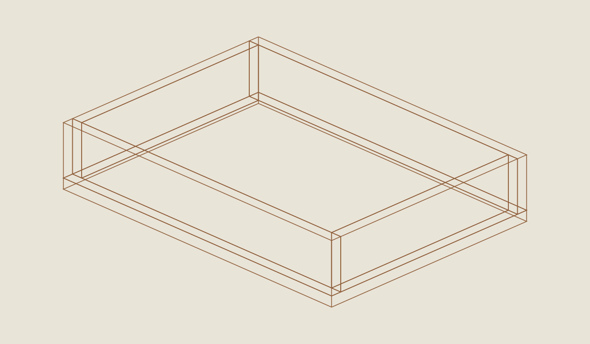
Loading the 3D view…
Drag to turn. Pinch or use + / − to zoom. The written step covers workholding and tool use.
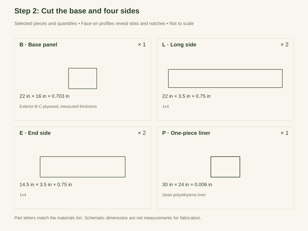
Scroll or swipe the enlarged drawing to read its dimensions. Choose Fit to see the whole drawing again.
Check: One base, two long sides and two ends match the written cuts; all liner-contact edges are smooth.
- 03
Dry-clamp the side ring
Set L pieces outside the ends. E pieces fit between them. Check 22 × 16 outside and 20-1/2 × 14-1/2 inside. Match the two diagonals; the ideal outside diagonal is √740 = 27.203 inches. The proposed shop target is a diagonal difference within 1/16 inch. Set the ring on B and confirm that all four outer faces align with the base edges.
Close-up · Whole model shows the complete part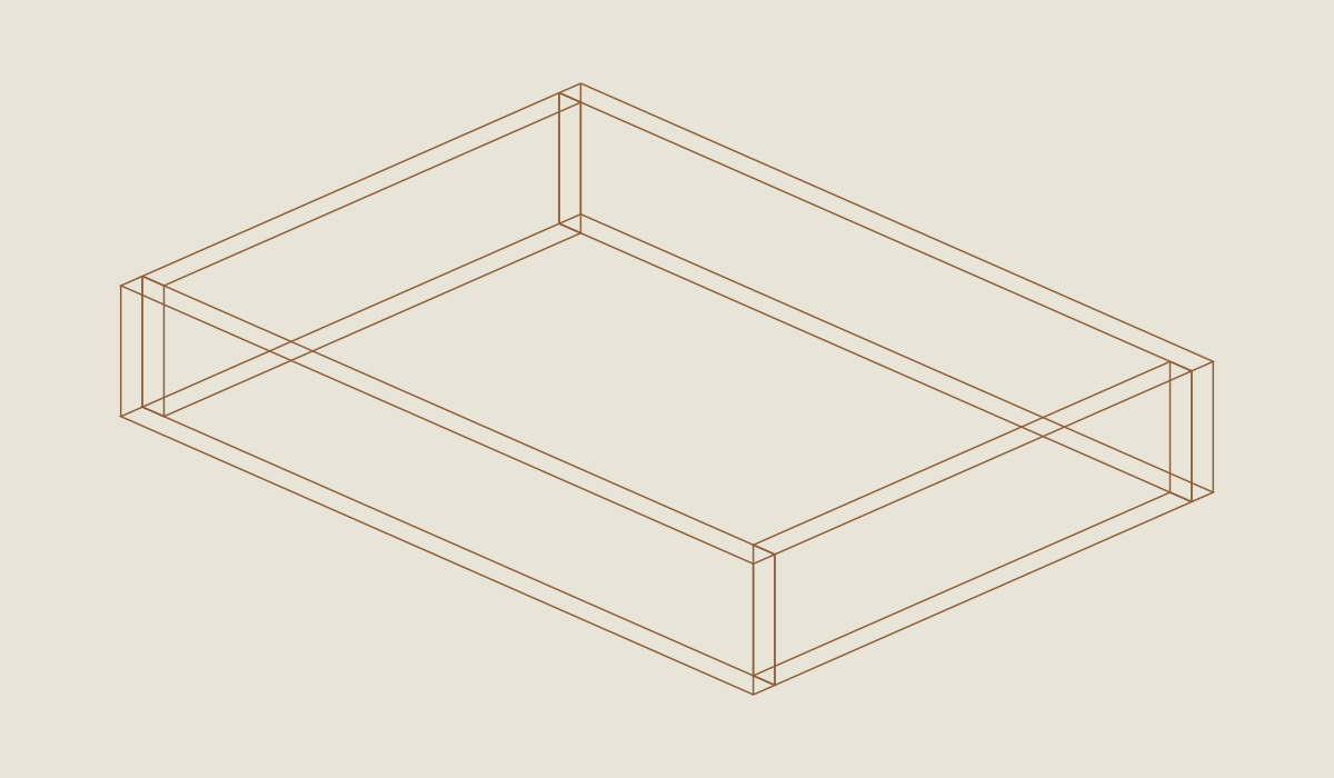
Loading the 3D view…
Drag to turn. Pinch or use + / − to zoom. The written step covers workholding and tool use.
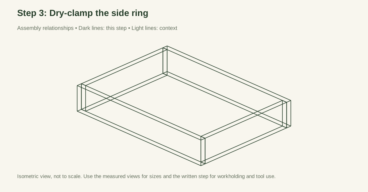
Scroll or swipe the enlarged drawing to read its dimensions. Choose Fit to see the whole drawing again.
Check: The four side faces align with the base perimeter; both ring diagonals agree before drilling.
- 04
Drill the corner joints
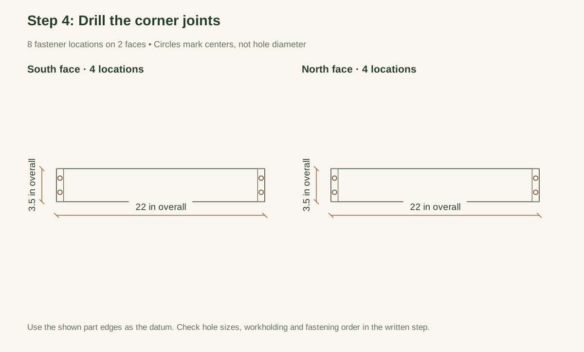
On each L face mark screw lines 3/8 inch from both ends, with holes 1 and 2-1/2 inches above its lower edge. There are two screws per corner. For a conventional #8 screw in this pine, trial a 7/64-inch receiving pilot and 11/64-inch clearance through L only, checking the actual fastener instructions. Countersink shallowly; keep the ring clamped so E cannot split or turn away.
Close-up · Whole model shows the complete part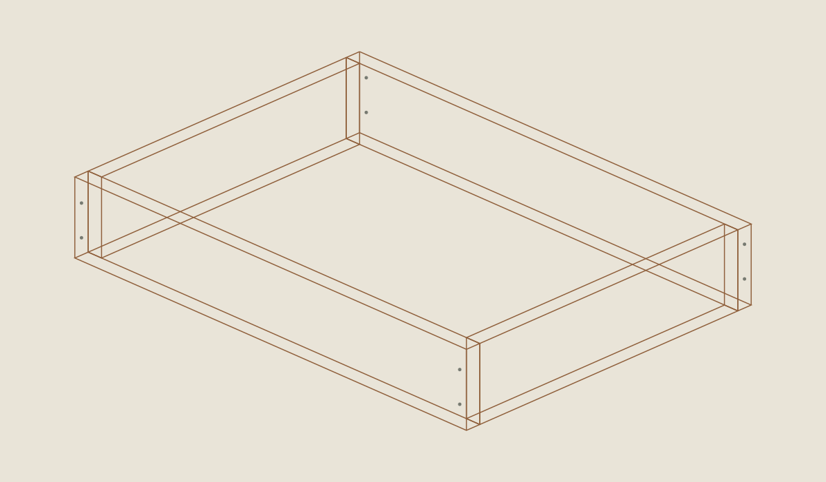
Loading the 3D view…
Drag to turn. Pinch or use + / − to zoom. The written step covers workholding and tool use.
Scroll or swipe the enlarged drawing to read its dimensions. Choose Fit to see the whole drawing again.
Check: Each corner has two marked screws entering the receiving end grain, with trial-tested pilots and no edge breakout.
- 05
Assemble the ring with eight screws
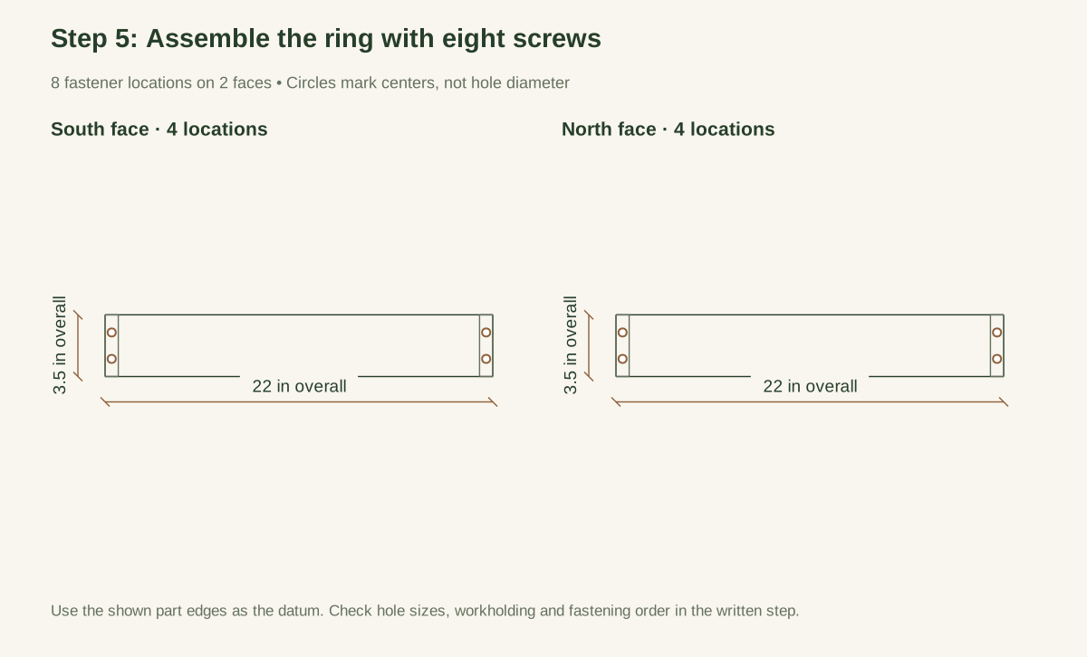
Drive the corner screws under controlled torque until heads are flush. Recheck square after the first two corners and after all four. Reject a cracked end or a joint that remains open when the clamp is removed. The liner must not be asked to cover a structurally loose or sharp corner.
Close-up · Whole model shows the complete part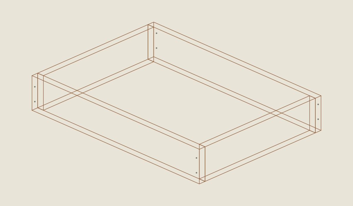
Loading the 3D view…
Drag to turn. Pinch or use + / − to zoom. The written step covers workholding and tool use.
Scroll or swipe the enlarged drawing to read its dimensions. Choose Fit to see the whole drawing again.
Check: Eight body screws hold the ring square; no corner opens after clamps are removed.
- 06
Mark the floor screw pattern
On the underside of B, mark long-wall screw lines 3/8 inch from the long edges. On each line use x stations 2, 5-1/2, 9, 13, 16-1/2, and 20 inches from one 22-inch end: twelve screws. For the short sides, use lines 3/8 inch from the short edges, with y stations 5 and 11 inches: four more. Every upward screw enters the lower edge of a side board, not the hollow interior.
Close-up · Whole model shows the complete part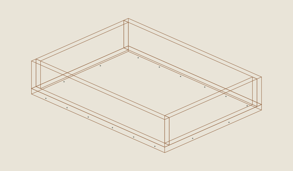
Loading the 3D view…
Drag to turn. Pinch or use + / − to zoom. The written step covers workholding and tool use.
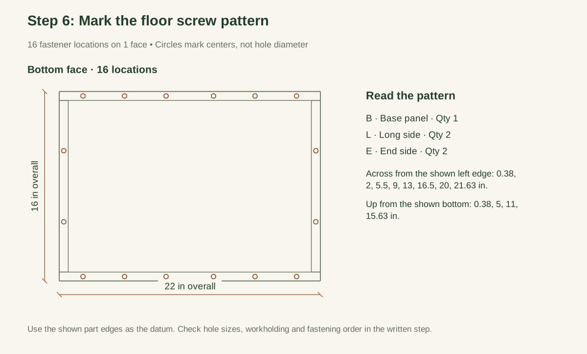
Scroll or swipe the enlarged drawing to read its dimensions. Choose Fit to see the whole drawing again.
Check: All sixteen floor fixing locations line up with the side-board lower edges, not the empty tray center.
- 07
Drill and attach the floor
Clamp the base to the ring, with the intended interior face up when assembled. Drill floor clearance holes and controlled receiving pilots separately; use a stop to prevent accidental emergence into the tray. Countersink underside heads just flush so they do not scratch the supporting surface. Install the sixteen floor screws, working around opposite sides rather than pulling one side tight first. Do not drive screws into an unmarked, guessed wall edge.
Close-up · Whole model shows the complete part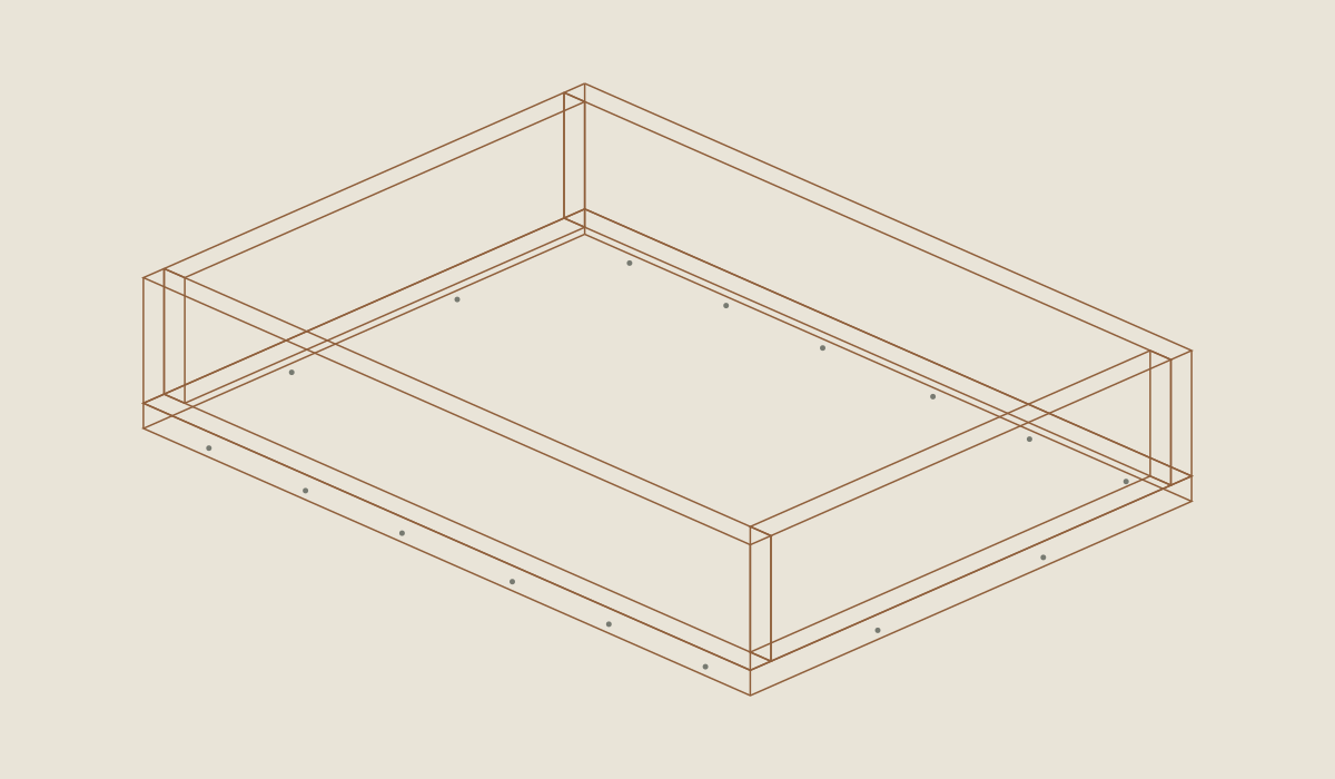
Loading the 3D view…
Drag to turn. Pinch or use + / − to zoom. The written step covers workholding and tool use.
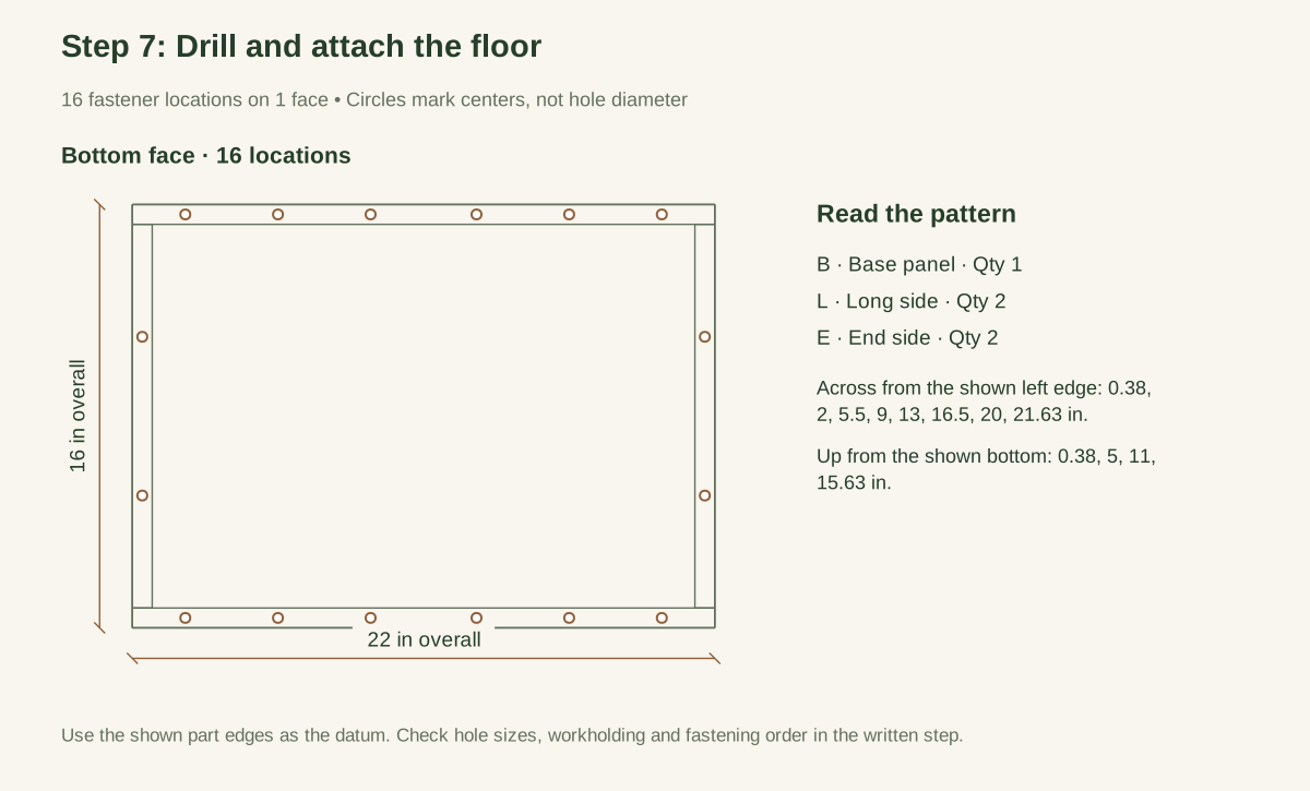
Scroll or swipe the enlarged drawing to read its dimensions. Choose Fit to see the whole drawing again.
Check: Sixteen floor screws seat flush from below with no point inside the tray; the base is flat.
- 08
Inspect before adding the liner
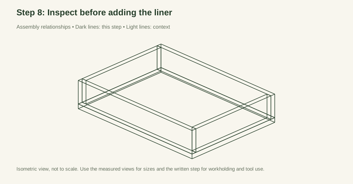
Place the tray upright on a flat surface and check for rocking. Inspect inside corners and the floor for projecting points or splinters. Confirm there are 24 installed screws. Inspect the bare interior and underside before the liner hides them. A warped base should be replaced, not forced flat by filling the tray.
Close-up · Whole model shows the complete part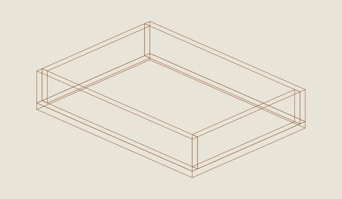
Loading the 3D view…
Drag to turn. Pinch or use + / − to zoom. The written step covers workholding and tool use.
Scroll or swipe the enlarged drawing to read its dimensions. Choose Fit to see the whole drawing again.
Check: The bare interior has no splinters, projecting metal or open seam that would damage a liner.
- 09
Mark the liner's central rectangle
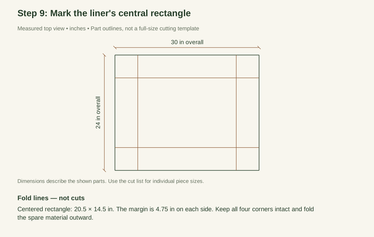
Lay out the 30 × 24 sheet on a clean table. Mark a central 20-1/2 × 14-1/2 floor rectangle: its edges lie 4-3/4 inches in from each outer sheet edge. That margin provides 3-1/2 inches for the wall, 3/4 for the top rim, and 1/2 inch down the outside. The liner pattern is derived from the clear tray geometry, not from its outside dimensions.
Close-up · Whole model shows the complete part
Loading the 3D view…
Drag to turn. Pinch or use + / − to zoom. The written step covers workholding and tool use.
Scroll or swipe the enlarged drawing to read its dimensions. Choose Fit to see the whole drawing again.
Keep the corners intact; the flat sheet folds into the finished tray.
Check: The marked liner center matches the actual inside floor; margins include the walls and outside clip allowance.
- 10
Fold rather than slit
Set the central rectangle onto the tray floor. Bring the sheet up each wall. At each corner, fold the excess into a flat triangular pleat against the end wall; do not cut a diagonal slit. A slit would create a route for damp material to reach the wood. Keep the floor smooth enough for a scoop without pulling the sheet tight across a sharp corner.
Close-up · Whole model shows the complete part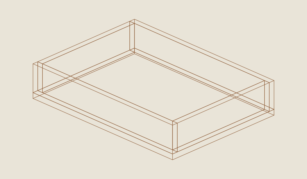
Loading the 3D view…
Drag to turn. Pinch or use + / − to zoom. The written step covers workholding and tool use.
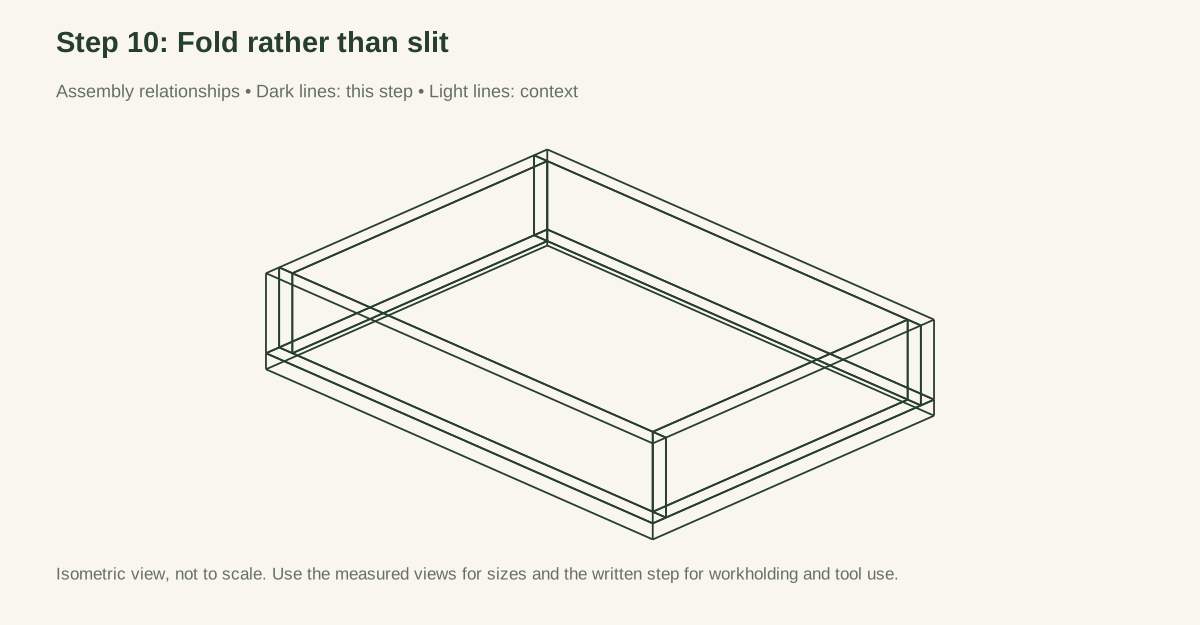
Scroll or swipe the enlarged drawing to read its dimensions. Choose Fit to see the whole drawing again.
Check: The four liner corners remain folded and uncut, with slack for the floor to lie against its support.
- 11
Clip the outside overhang
Fold the liner over the rim and fit two padded clips per side. Keep clips where they do not obstruct the working hand or fall into the medium. No screw or staple passes through the liner. Adjust pleats until the liner rests on the floor rather than hanging from the clips. Check that a clip cannot easily be knocked into the tray.
Close-up · Whole model shows the complete part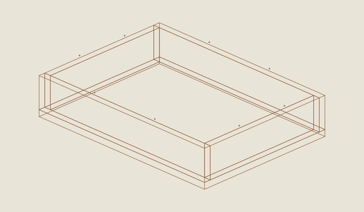
Loading the 3D view…
Drag to turn. Pinch or use + / − to zoom. The written step covers workholding and tool use.
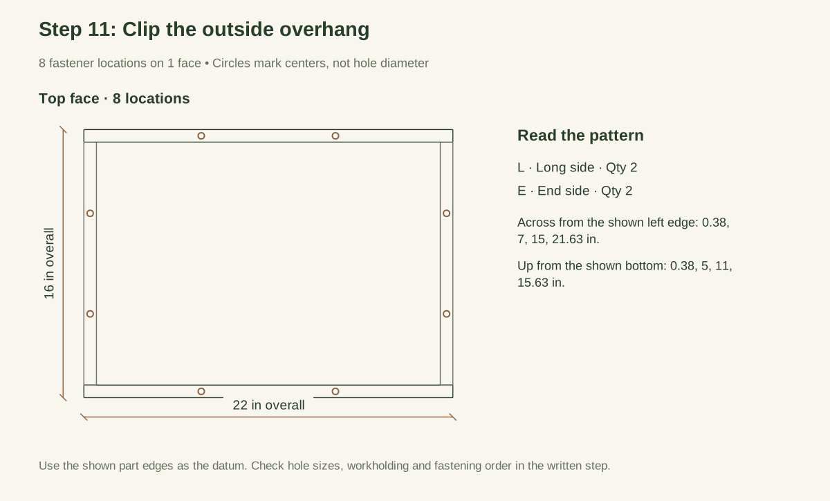
Scroll or swipe the enlarged drawing to read its dimensions. Choose Fit to see the whole drawing again.
Clip geometry is schematic; the supplied clips must fit the actual wall and liner.
Check: All clips retain the outside overhang and can be removed without dropping into the mix.
- 12
Try a small dry batch first
On the fully supporting surface, add a small scoop of clean dry medium and turn it with a blunt scoop. Empty it into a separate container and check for punctures, trapped grains, or awkward corners. Then trial a modest amount of damp—not flooded—medium. Record the result. This is a handling observation, not proof that the tray can retain water or be carried full.
Close-up · Whole model shows the complete part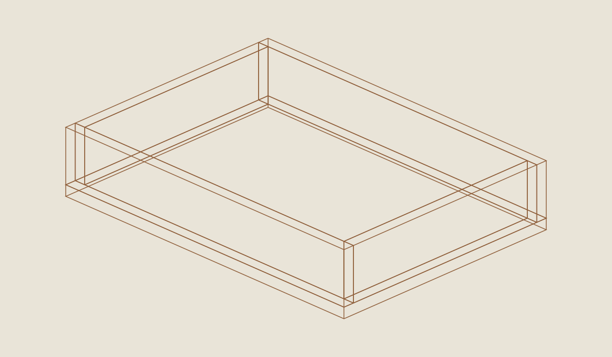
Loading the 3D view…
Drag to turn. Pinch or use + / − to zoom. The written step covers workholding and tool use.
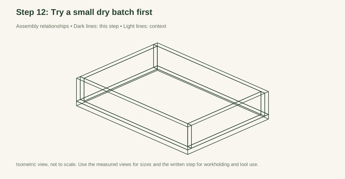
Scroll or swipe the enlarged drawing to read its dimensions. Choose Fit to see the whole drawing again.
Check: The supported dry trial leaves no torn liner, trapped sharp grit or inaccessible corner; empty before lifting.
05 / Keep it sound
Care
After the build
- Rest the entire base on a suitable surface and keep each batch below the 2-inch working line. That is about 0.344 cubic foot, so a full one-cubic-foot bag is more than one batch.
- Seat the folded liner on the floor before clipping it; empty the tray before moving it or removing the liner.
Check it each season
- Add components in measured small scoops. Follow the selected crop/medium recipe rather than treating this guide as a universal soil formula. Keep below the 2-inch working line. Do not chop material with a sharp blade against the liner, stand on the tray, or lift a batch by pulling the rim.
- Scoop the finished mix into pots while the tray stays supported. Remove all material before moving it. Unclip and lift out the empty liner, brush the wooden corners, and dry both separately. Store the tray indoors or under genuinely dry cover with the liner removed. Replace torn liner material rather than patching a repeatedly wet corner with tape of unknown suitability.
- The compost screen can help prepare suitable mature compost before mixing; support it independently rather than assuming this tray's rim is a tested stand. The low raised bed is a ground-supported growing structure, not a larger version of this lined tray.
If something looks wrong
- Damp plywood under liner
- Check: Puncture, cut corner, trapped wet residue. Fix: Empty, remove liner, dry the wood, and replace the liner.
- Scoop catches liner
- Check: Sheet suspended or pleat in working area. Fix: Refit with the floor supported and pleats against end walls.
- Floor rocks
- Check: Warp or proud underside screw. Fix: Correct before use; never load it to flatten it.
- Side separates
- Check: Missed receiving pilot, split end, failed screw. Fix: Stop, empty, and replace damaged parts.
- Liner smells or remains dirty
- Check: Inadequate cleaning/drying. Fix: Replace it and correct storage; do not reuse for food.
Keep exploring