Compost projects · Guide 67
How to Build a Compost-Sifting Screen with Replaceable Mesh
Make a 20 × 14-inch compost screen with a clear opening, protected mesh edges, and separate screw schedules for the frame and removable retainers.
01 / See the shape
View the project
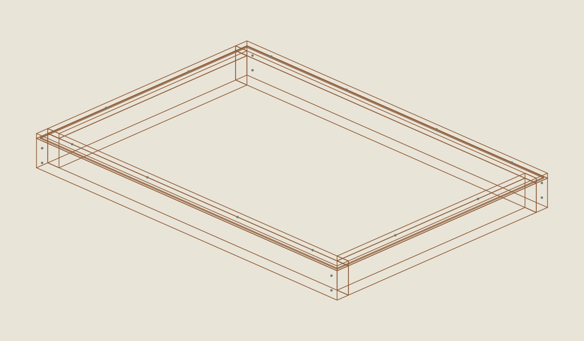
Loading the 3D view…
Drag to turn. Pinch or use + / − to zoom. The written step covers workholding and tool use.
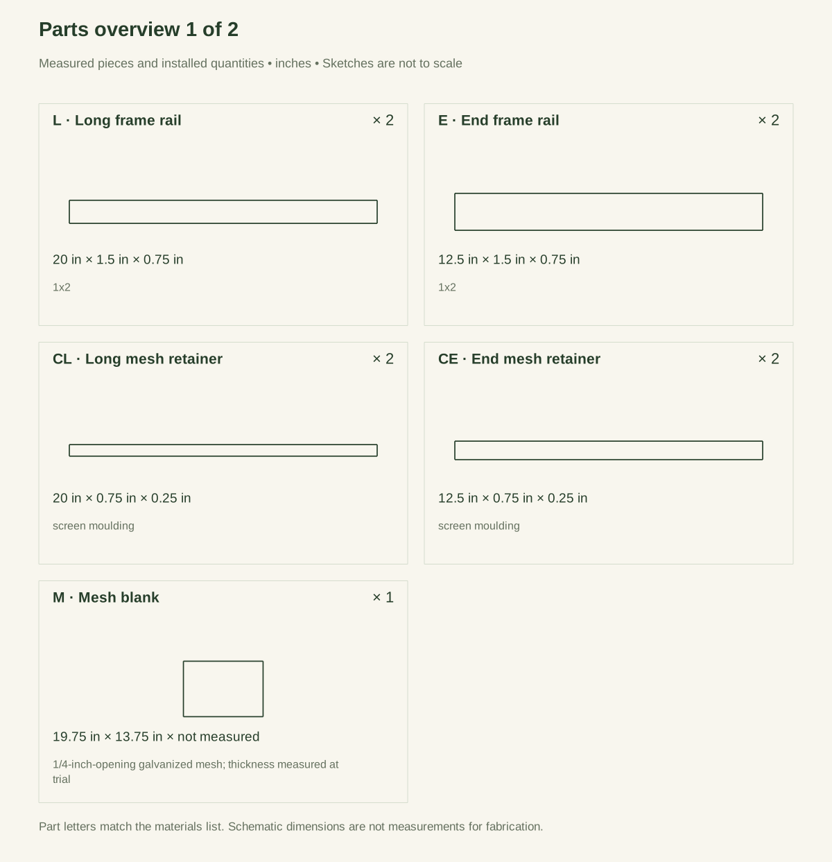
Scroll or swipe the enlarged drawing to read its dimensions. Choose Fit to see the whole drawing again.
Compost-sifting screen. Check the dimensions and build steps before cutting.
02 / Plan your build
Before you start
A useful compost screen separates coarse pieces without making the gardener handle a sharp wire rim. In this design, a small wooden frame carries quarter-inch mesh, and four removable strips capture its perimeter from underneath. When the mesh wears out, those strips can be unscrewed instead of tearing staples out of the frame.
This is for small amounts of already finished garden compost, not rocks, construction debris, contaminated soil, food preparation, or standing loads. EPA describes quarter-inch hardware cloth as an option for a homemade compost screener. That supports the screening method, not a load rating for this original frame.
Where it goes
A stable, supported work area for small batches of finished garden compost. Not for rocks, construction debris, contaminated soil, food preparation, or standing on. Store it dry.
Footprint: 20 × 14 inches.
What to expect
Accurate square cuts, small pilots, and controlled sharp-mesh handling. Plan 90–150 working minutes.
A planning estimate for the hands-on work, once the materials are bought and the tools are set up. It has not been timed on a finished build.
Check the spot
- A stable, supported work area for small batches of finished garden compost. Not for rocks, construction debris, contaminated soil, food preparation, or standing on. Store it dry.
- Measure the boards, mesh, and hardware you actually bought before you cut. Keep other people back while you cut wood and trim the mesh; cut wire ends are sharp.
Stop and check first if…
- Stop if any cut wire, proud screw, split rail, loose retainer, or catching edge remains accessible.
- The 1-3/4-inch figure is the wood frame only. The finished height also includes the mesh, so measure it after assembly.
- No filled lifting capacity has been established. Work in small batches.
- Do not build the frame from MDF, badly splintered pallet scraps, or painted wood of unknown history.
Work safely
- Use a tape, square, clamps, supported saw, drill/driver, countersink, matching driver bit, wire cutters suitable for the mesh, pliers, and a brush. Use eye protection throughout cutting and drilling. Wear cut-resistant gloves for mesh handling, but do not wear loose gloves near rotating bits. Clamp small wooden parts to a sacrificial backing or fixture instead of holding them in your hand; a drill can catch and spin unsecured work.
- Cover the work surface so wire trimmings are easy to collect. Keep the wire-cutting operation separate from the wood assembly area. A sharp clipped strand on the floor remains a hazard after the screen itself is finished.
- Stop if any cut wire, proud screw, split rail, loose retainer, or catching edge remains accessible.
- The 1-3/4-inch figure is the wood frame only. The finished height also includes the mesh, so measure it after assembly.
- No filled lifting capacity has been established. Work in small batches.
- Do not build the frame from MDF, badly splintered pallet scraps, or painted wood of unknown history.
Budget
We have not put a price on this one yet. Lumber and hardware prices change by store and season, so price the list under What you need at your local supplier before you buy.
03 / Gather and cut
What you need
Frame rails
1 board
Straight untreated pine 1 × 2; actual 0.75 × 1.5 inches. One 8-foot length.
Cut two 20-inch L rails and two 12.5-inch E rails: 65 inches plus four kerfs and end trimming.
Mesh-retainer moulding
1 length
Pine screen moulding; measured section 0.75 × 0.25 inch. One 8-foot length.
Cut two 20-inch CL and two 12.5-inch CE strips. Do not use the frame screws in these thin retainers.
Screen mesh
1 blank
Galvanized hardware cloth with 1/4-inch openings; measure actual wire/capture thickness. A clean piece yielding 19.75 × 13.75 inches.
Center at a 1/8-inch outside inset. All cut ends must be captured; mesh thickness is not zero in the physical stack.
Frame screws
8 screws
#6 × 1.5-inch Type 316 stainless flat-head wood screws. Package of at least eight.
Two per frame corner. Follow the screw maker’s pilot instructions.
Retainer screws
12 screws
#6 × 0.75-inch Type 316 stainless flat-head wood screws. Package of at least twelve.
Keep separate from longer frame screws. No glue, staples, exposed ties, or handles are included.
Cut list
| Piece | How many | Cut length | Note |
|---|---|---|---|
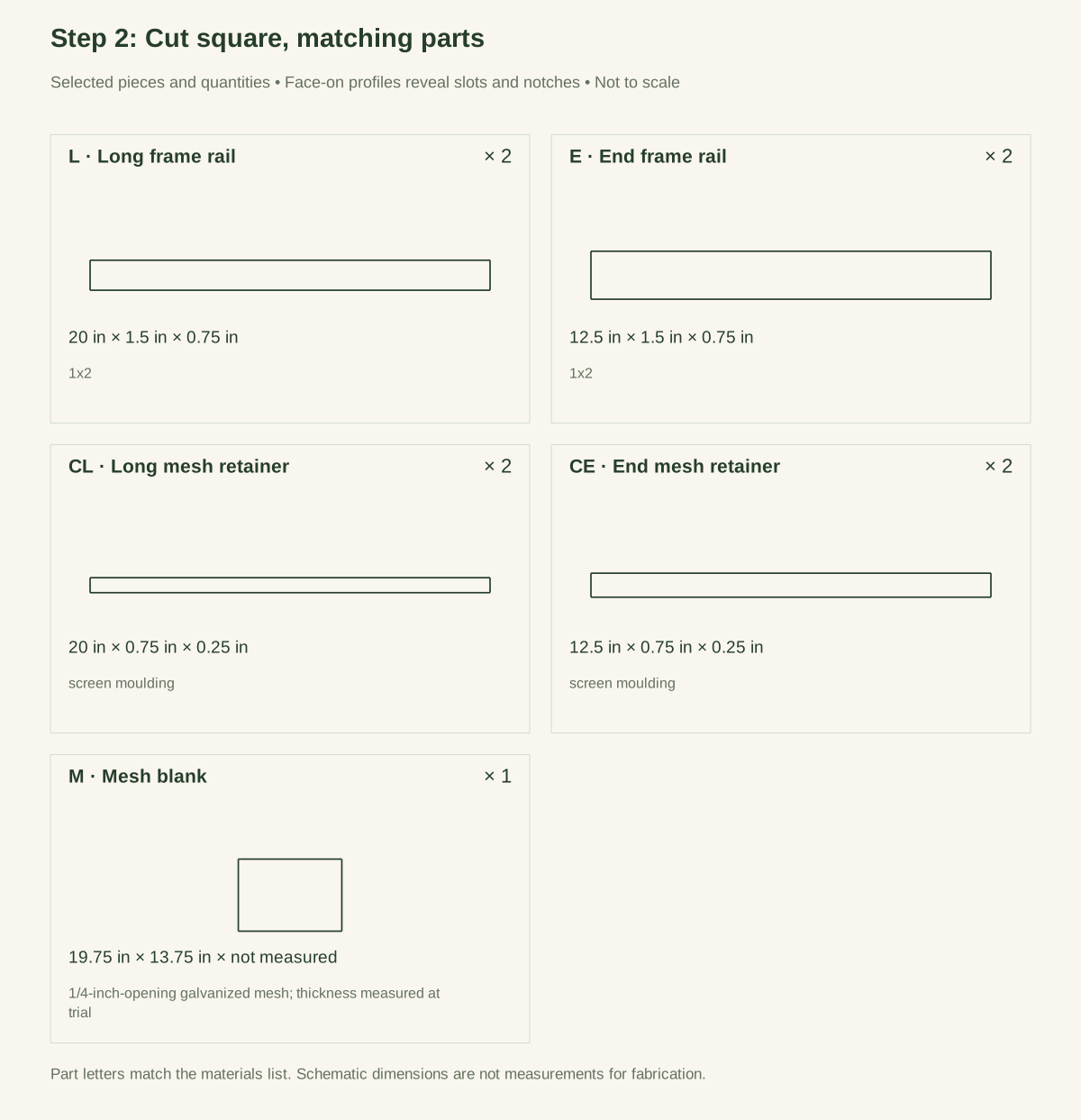
| L — Long frame rail | 2 | 20 in | Part L, cut from 1x2. Size: 20 × 1.5 × 0.75 in. Check the plan sheets for its reference edges and any shaped detail. |
| E — End frame rail | 2 | 12.5 in | Part E, cut from 1x2. Size: 12.5 × 1.5 × 0.75 in. Check the plan sheets for its reference edges and any shaped detail. |
| CL — Long mesh retainer | 2 | 20 in | Part CL, cut from screen moulding. Size: 20 × 0.75 × 0.25 in. Check the plan sheets for its reference edges and any shaped detail. |
| CE — End mesh retainer | 2 | 12.5 in | Part CE, cut from screen moulding. Size: 12.5 × 0.75 × 0.25 in. Check the plan sheets for its reference edges and any shaped detail. |
| M — Mesh blank | 1 | 19.75 in | Part M, cut from 1/4-inch-opening galvanized mesh; thickness measured at trial. Size: 19.75 × 13.75 in. Check the plan sheets for its reference edges and any shaped detail. The drawings show this part with no thickness. Measure the actual wire or trim you bought and allow for it before you assemble. |
Tools
- Tape or rule, square, and pencil
- Clamps and stable supported work surface
- Suitable saw with its required guarding
- Drill/driver, selected-product pilot and clearance bits, and countersink
- Abrasives for hand-contact edges
- Wire cutters matched to the selected mesh
- Flat support for safely capturing the mesh perimeter
Protective gear
- Eye protection for cutting and drilling; match other protection to the actual tool instructions.
- Appropriate hearing protection and wood-dust control for the selected cutting method.
- Cut-resistant gloves for handling and trimming the mesh; take them off before you run a saw or drill.
04 / Put it together
Build steps
- 01
Measure the actual sections
Check the rail thickness and moulding width with a rule or caliper. The 12-1/2-inch ends are derived from 14 − 2 × 0.75. If the rails are thicker or thinner, revise the end length and mesh overlap before cutting. Reject a moulding piece that is too narrow to cover the mesh perimeter or too split to hold screws.
Close-up · Whole model shows the complete part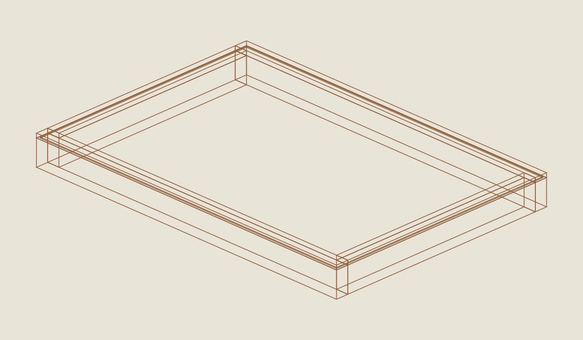
Loading the 3D view…
Drag to turn. Pinch or use + / − to zoom. The written step covers workholding and tool use.
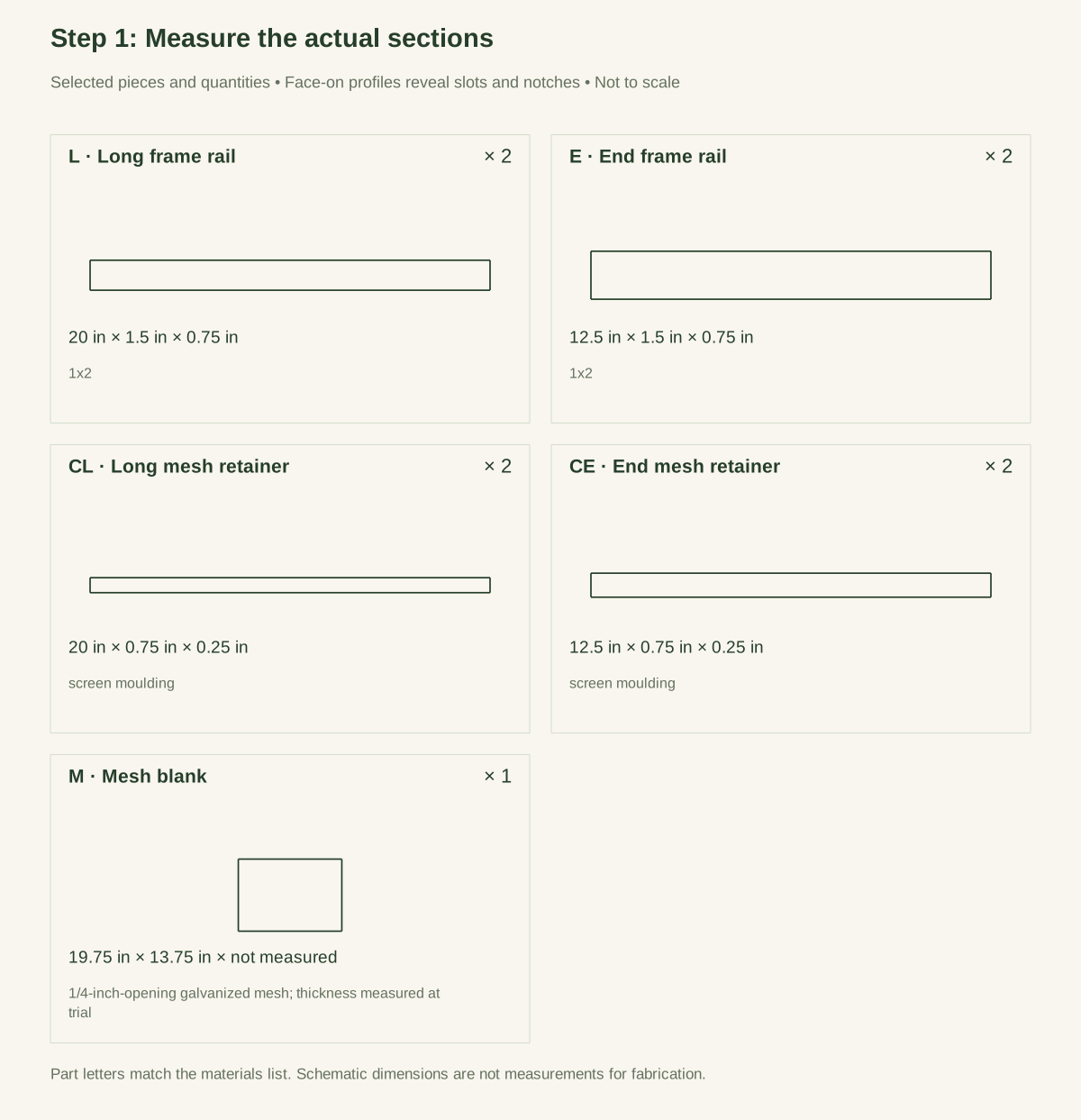
Scroll or swipe the enlarged drawing to read its dimensions. Choose Fit to see the whole drawing again.
Check: Actual frame and capture-strip sections match the cut list; reject twisted or split stock.
- 02
Cut square, matching parts
Cut L, E, CL, and CE to the schedule and label the hidden faces. Compare both long rails and both end rails face to face. Keep like lengths within 1/32 inch as a shop target. Ease exposed outer edges only; leave the underside capture faces flat so the retainers can bear evenly.
Close-up · Whole model shows the complete part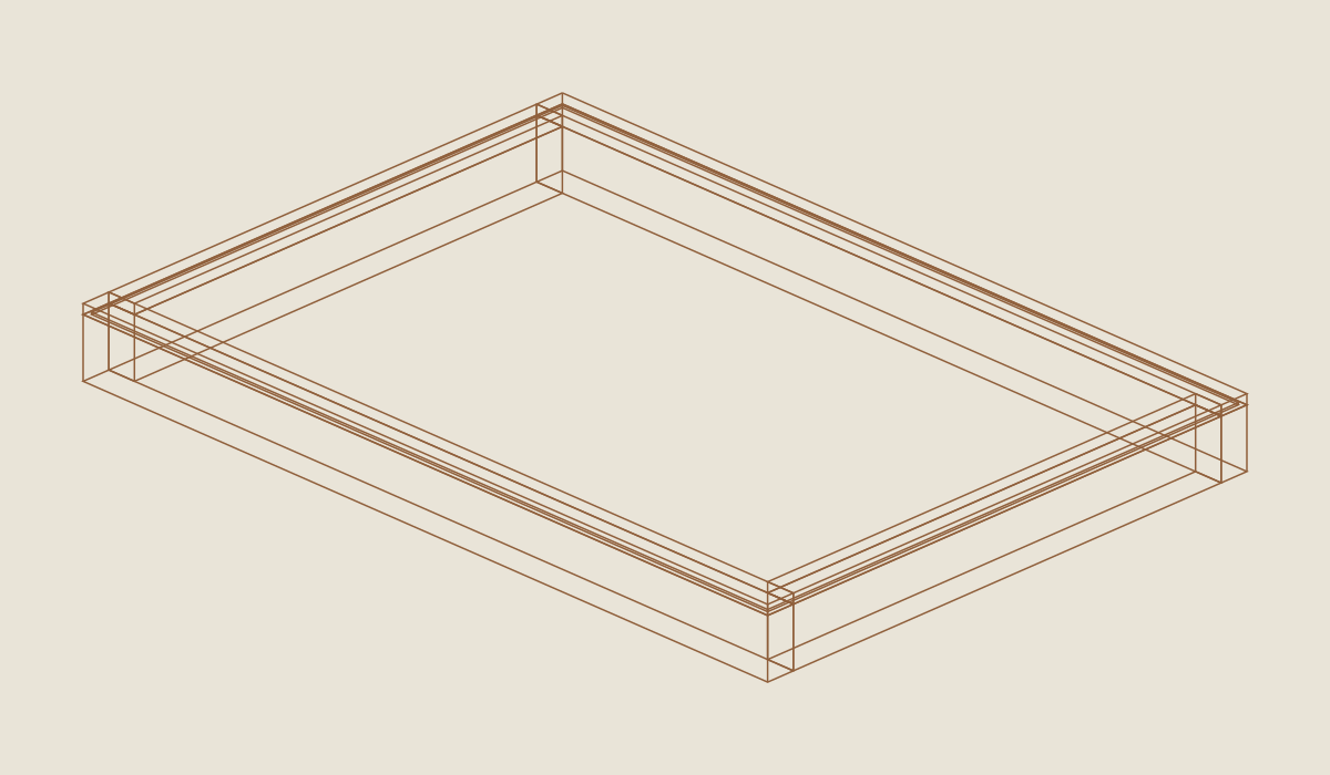
Loading the 3D view…
Drag to turn. Pinch or use + / − to zoom. The written step covers workholding and tool use.
Scroll or swipe the enlarged drawing to read its dimensions. Choose Fit to see the whole drawing again.
Check: Two long rails, two end rails and four capture strips are labeled; like cuts match within 1/32 inch.
- 03
Clamp the frame with long rails running through
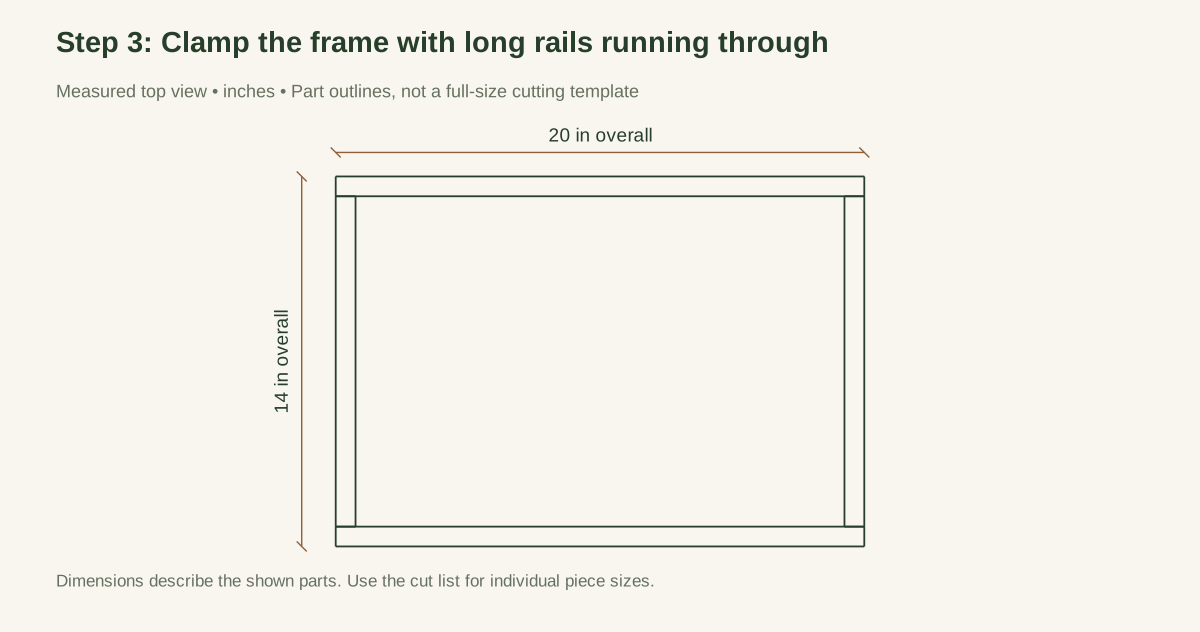
Lay the long rails on edge, parallel. Fit the E rails between them at the ends. Clamp on a flat surface and check 20 × 14 outside and 18-1/2 × 12-1/2 inside. Both outside diagonals should match; the ideal diagonal is √(20² + 14²) = 24.413 inches. A difference of no more than 1/16 inch is the proposed shop target for this small frame.
Close-up · Whole model shows the complete part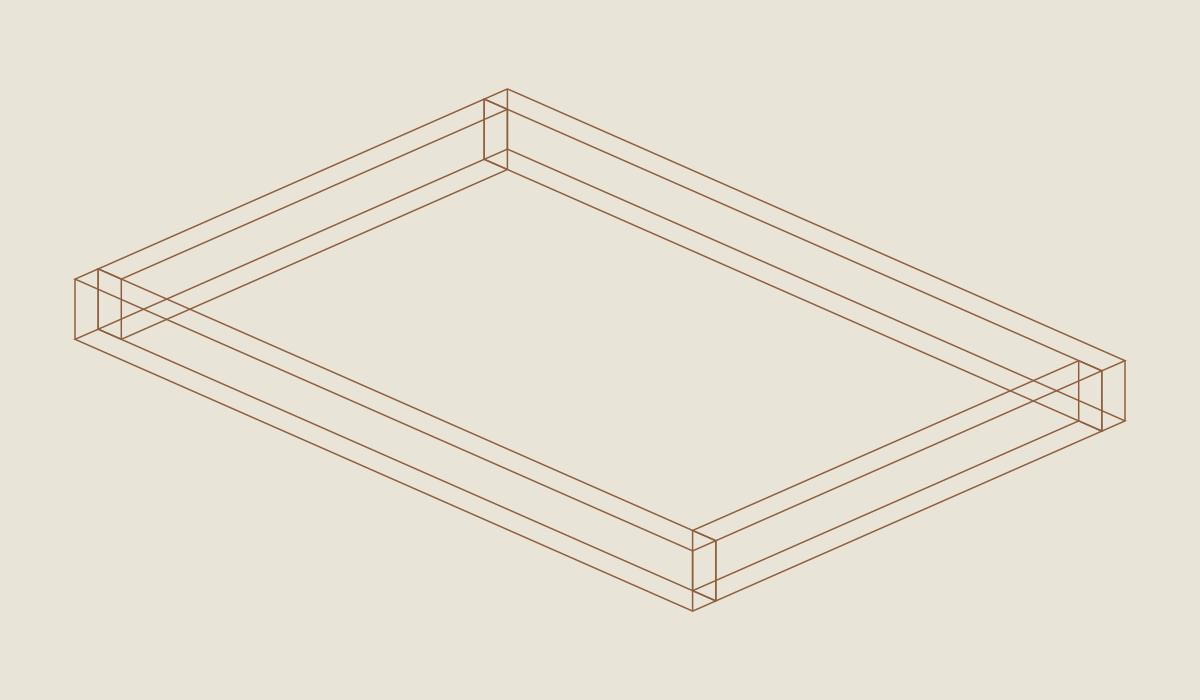
Loading the 3D view…
Drag to turn. Pinch or use + / − to zoom. The written step covers workholding and tool use.
Scroll or swipe the enlarged drawing to read its dimensions. Choose Fit to see the whole drawing again.
Check: Frame outside is 20 × 14 inches; ends fit between long rails and diagonals agree near 24.413 inches.
- 04
Mark the corner screws
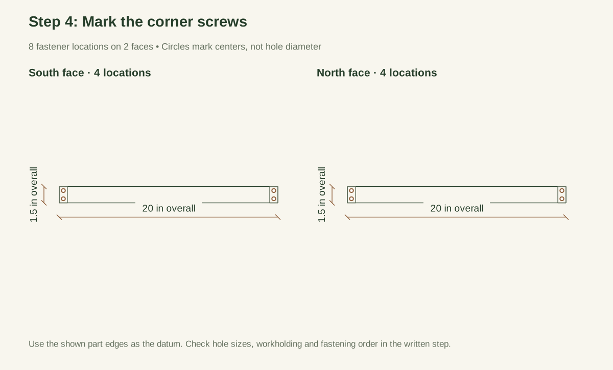
On the outside face of each L rail, mark a screw line 3/8 inch from each end. Put two holes on each line, 3/8 and 1-1/8 inches above the rail bottom. The screws pass through the long rail into the end grain of E. Keep the frame clamped while drilling so the narrow receiving piece cannot turn away.
Close-up · Whole model shows the complete part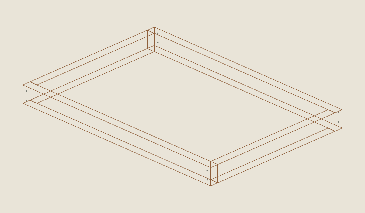
Loading the 3D view…
Drag to turn. Pinch or use + / − to zoom. The written step covers workholding and tool use.
Scroll or swipe the enlarged drawing to read its dimensions. Choose Fit to see the whole drawing again.
Check: All eight corner screw centers enter the end rails without crossing a cut edge.
- 05
Drill a trial joint, then assemble
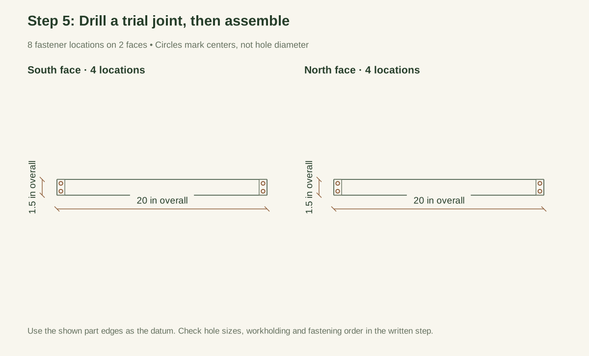
For conventional #6 screws in this softwood, start a scrap trial with a 5/64-inch receiving pilot and a 9/64-inch clearance hole through L only. Use the actual screw manufacturer's instruction if it differs. Countersink lightly for a flush head. If the receiving wood splits, the screw strips, or excessive torque is needed, correct the setup before using the real parts.
Install all eight F1 screws, keeping the diagonals matched. No screw should project into the clear opening. Check the joints after releasing the clamps. A racked or flexible frame needs correction before it receives mesh; the mesh is not a substitute for a sound frame.
Close-up · Whole model shows the complete part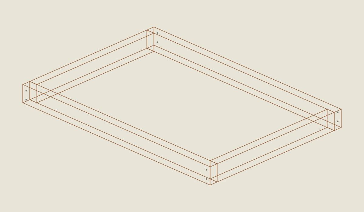
Loading the 3D view…
Drag to turn. Pinch or use + / − to zoom. The written step covers workholding and tool use.
Scroll or swipe the enlarged drawing to read its dimensions. Choose Fit to see the whole drawing again.
Check: The scrap joint accepts the selected pilot; all eight frame screws seat without splitting or twisting the frame.
- 06
Measure the assembled frame before cutting wire
Invert the frame. Confirm the actual outside measurements, then mark a mesh blank 1/4 inch smaller in each overall dimension: 19-3/4 × 13-3/4 for this frame. Centering that blank gives a 1/8-inch inset from each outer edge and 5/8 inch of mesh beneath each 3/4-inch rail. These overlaps are the reason the wire is not cut to the clear opening.
Close-up · Whole model shows the complete part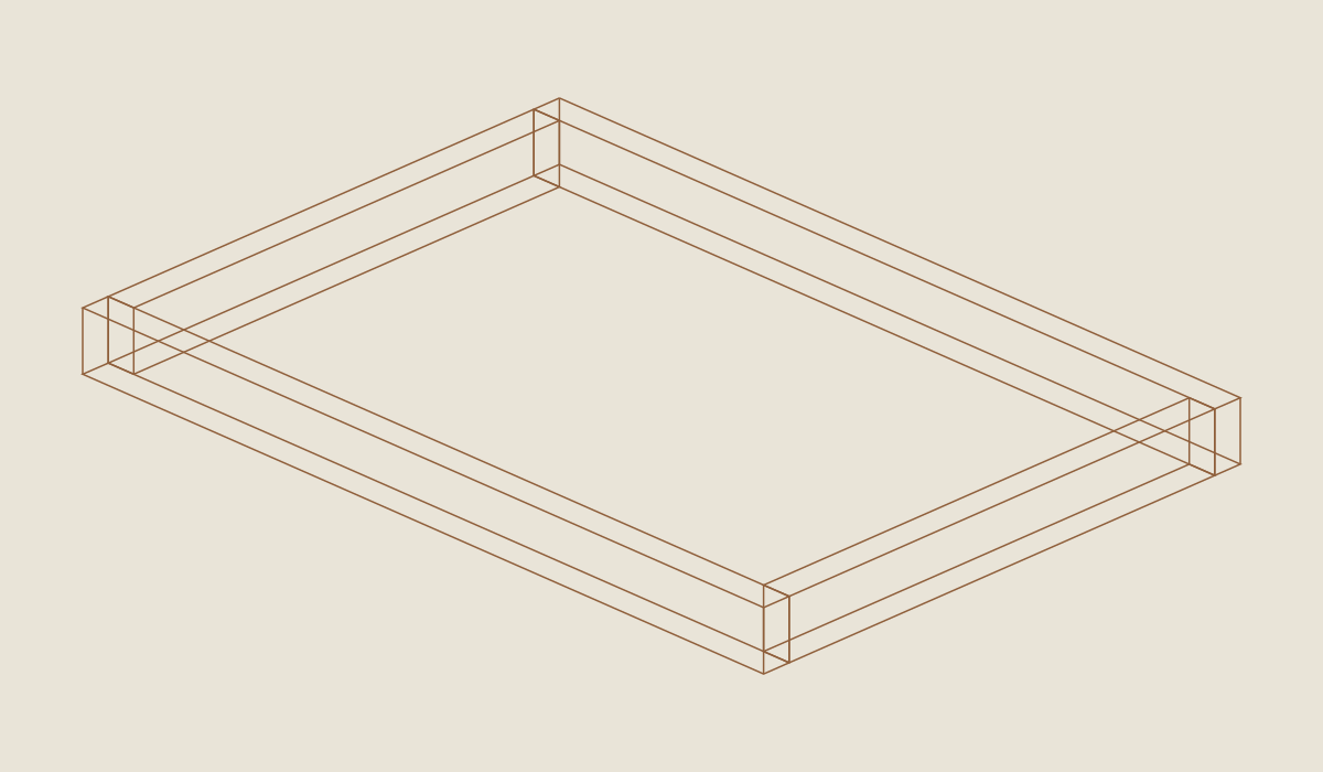
Loading the 3D view…
Drag to turn. Pinch or use + / − to zoom. The written step covers workholding and tool use.
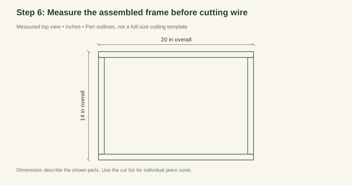
Scroll or swipe the enlarged drawing to read its dimensions. Choose Fit to see the whole drawing again.
Check: Mesh blank is 19-3/4 × 13-3/4 inches only when the assembled outside frame is exactly 20 × 14.
- 07
Cut and flatten the blank under control
Keep the sheet supported while using suitable wire cutters. Do not pull a cut strip off by tearing the welds. Collect every trimming. Flatten curls gently with pliers; do not hammer the mesh on a fragile surface. Inspect all four cut edges before bringing the blank to the frame.
Close-up · Whole model shows the complete part
Loading the 3D view…
Drag to turn. Pinch or use + / − to zoom. The written step covers workholding and tool use.
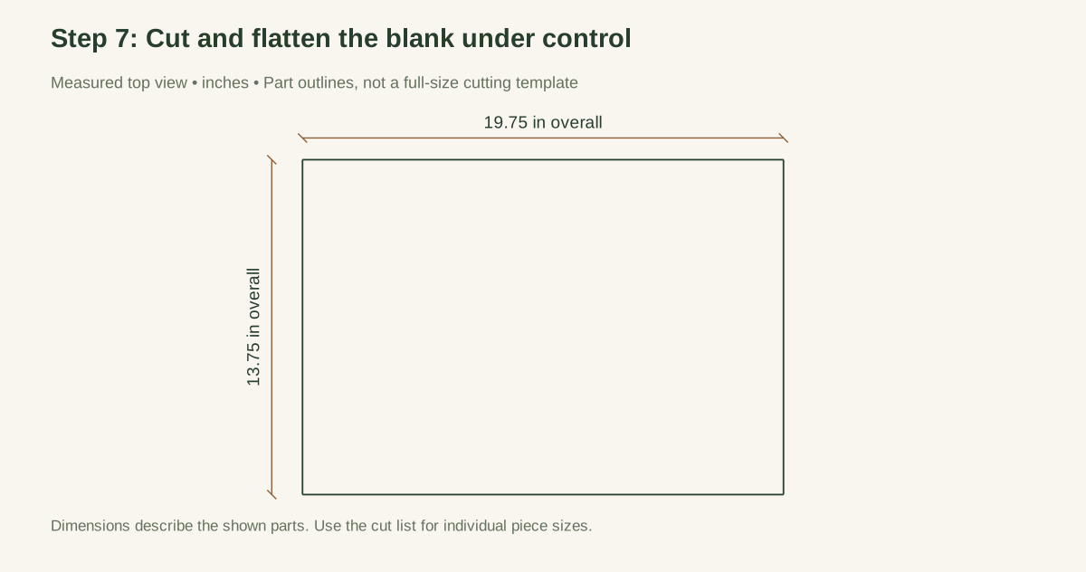
Scroll or swipe the enlarged drawing to read its dimensions. Choose Fit to see the whole drawing again.
Mesh outline shows coverage; its thickness and opening need the chosen product.
Check: The supported wire blank lies flat; no cut tip is loose or left where a hand will grip it.
- 08
Dry-fit all four capture strips
Place M against the underside and center it. Lay CL strips beneath the long rails and CE strips between them. The retainer outline should match the 20 × 14 frame, and every cut wire must sit behind solid wood. Reject a fit that leaves a wire tip at a corner. Do not compensate by bending an exposed tip outward where a hand could reach it.
Close-up · Whole model shows the complete part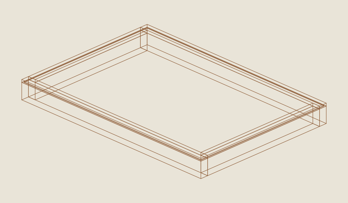
Loading the 3D view…
Drag to turn. Pinch or use + / − to zoom. The written step covers workholding and tool use.
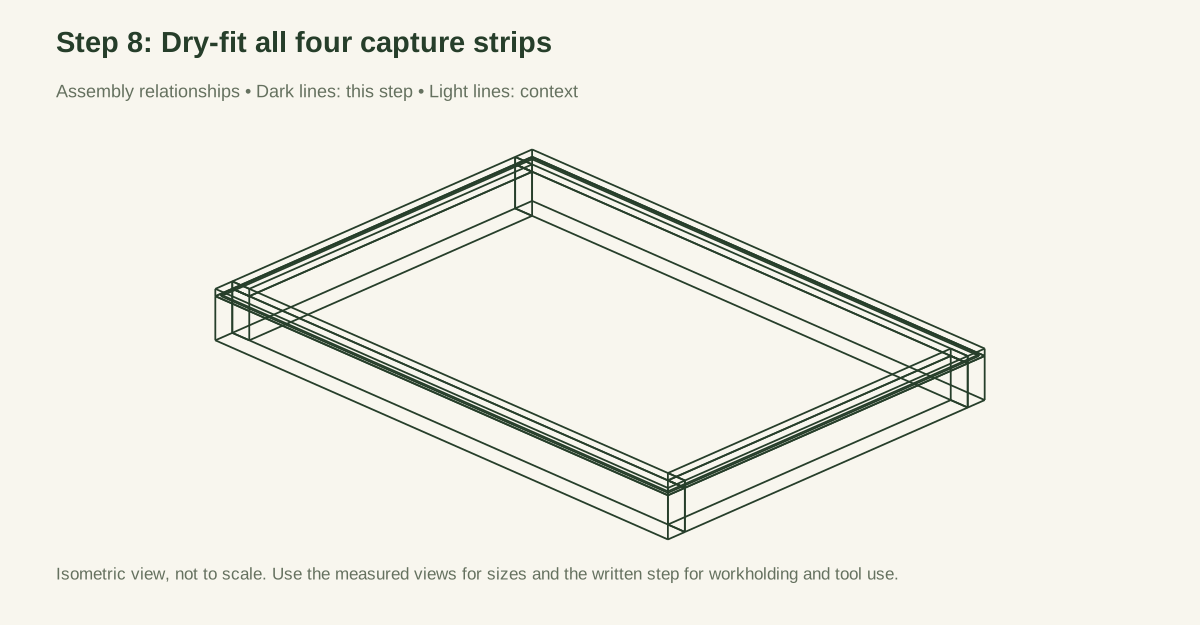
Scroll or swipe the enlarged drawing to read its dimensions. Choose Fit to see the whole drawing again.
Check: All cut mesh edges lie under the four capture strips; the strips seat without forcing the frame.
- 09
Mark the twelve retainer screws
On each CL strip, mark its width centerline 3/8 inch from the outer edge and positions 2, 7, 13, and 18 inches from the same end: eight screws altogether. On each CE strip, put two screws 3-1/2 and 9 inches from its end, also centered across the width. In the assembled 14-inch direction those stations are 4-1/4 and 9-3/4 inches from the frame's outside datum. That adds four screws, for 12 F2 screws total.
Close-up · Whole model shows the complete part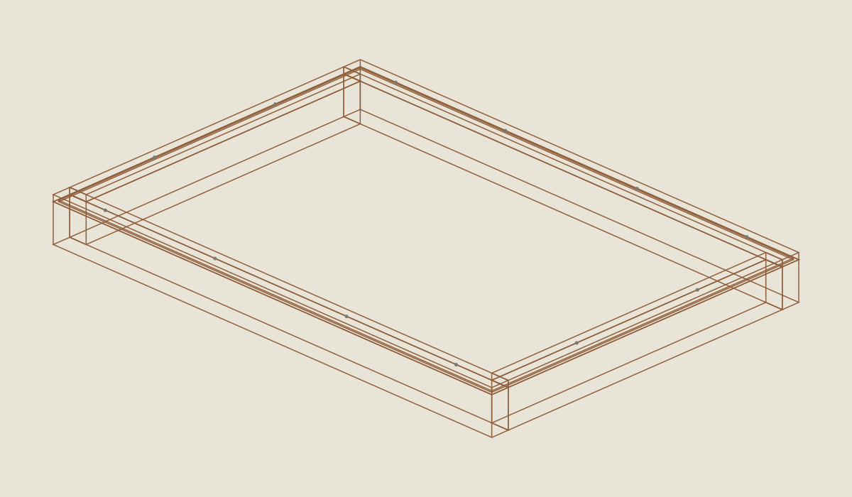
Loading the 3D view…
Drag to turn. Pinch or use + / − to zoom. The written step covers workholding and tool use.
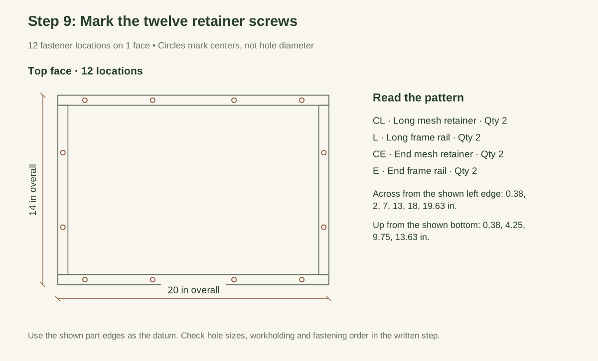
Scroll or swipe the enlarged drawing to read its dimensions. Choose Fit to see the whole drawing again.
Check: Eight long-strip and four end-strip screw stations give twelve retainer screws, with no corner collision.
- 10
Pilot through wood, not blindly into mesh wire
Clamp the capture strip and mark the receiving locations. Move a retainer screw slightly along its centerline only when needed to pass through a mesh opening, recording the final location; never use a drill bit to wind up a wire strand. Maintain at least 1 inch from a retainer end. Drill clearance through the strip and a controlled-depth pilot into the rail; use a stop so the bit cannot emerge through the upper rim. Seat the short screws flush without splitting the thin moulding.
Close-up · Whole model shows the complete part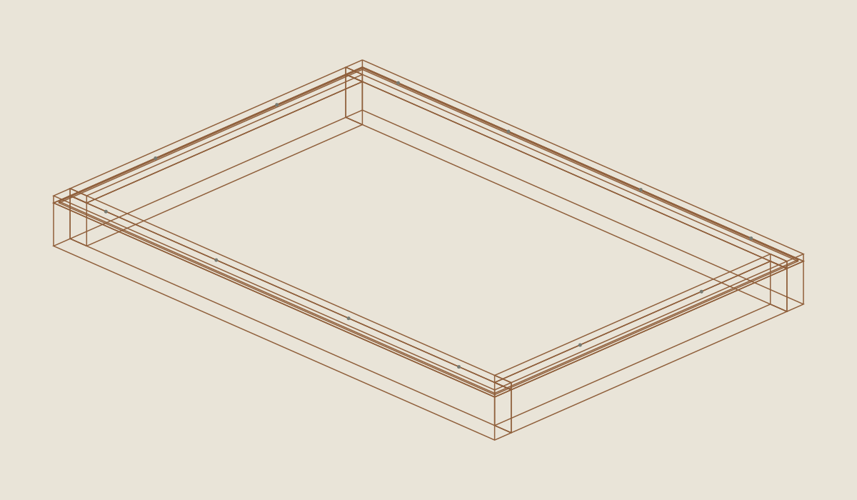
Loading the 3D view…
Drag to turn. Pinch or use + / − to zoom. The written step covers workholding and tool use.
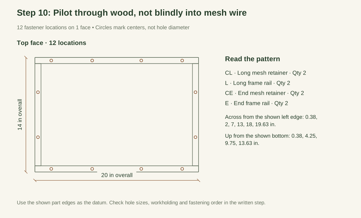
Scroll or swipe the enlarged drawing to read its dimensions. Choose Fit to see the whole drawing again.
Check: All twelve capture screws enter rail wood; no bit or screw breaks through the opposite hand-contact surface.
- 11
Inspect the entire perimeter
Check all corners and both faces with good light. There should be no loose mesh, projecting screw, exposed cut wire, or strip that can rock away from the frame. Slide a cloth around the rim to find snags. Measure and record the final overall height including the selected mesh; do not overwrite it with the nominal 1-3/4-inch wood stack.
Close-up · Whole model shows the complete part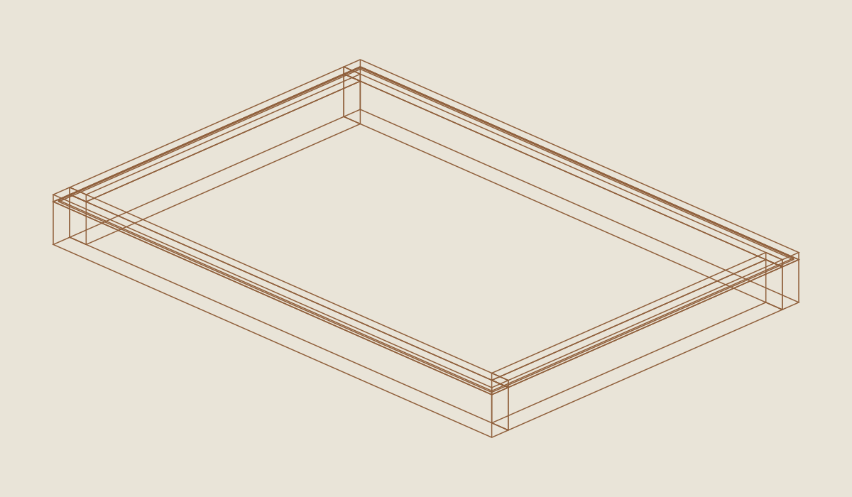
Loading the 3D view…
Drag to turn. Pinch or use + / − to zoom. The written step covers workholding and tool use.
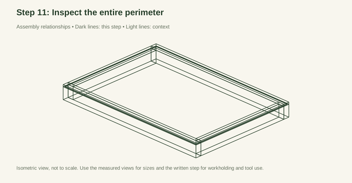
Scroll or swipe the enlarged drawing to read its dimensions. Choose Fit to see the whole drawing again.
Check: Eight frame screws and twelve retainer screws are present. Inspect the entire perimeter and measure the real height, including mesh.
05 / Keep it sound
Care
After the build
- Start with a small scoop of mature compost and gentle movement, and check the frame and mesh before working larger batches.
- Screening removes coarse pieces; it does not remove contamination or establish that compost is mature.
Check it each season
- Place the screen over a stable container or supported work surface that bears the wooden frame without rocking. Keep fingers away from its underside. Start with a small scoop of mature compost and gentle movement. Watch how it handles, whether the frame moves, and whether the mesh stays put. This first use is not a load test, and it does not give the screen a weight rating.
- Do not press stones through the mesh or strike the frame to clear it. Return appropriate coarse organic pieces to a composting process; discard litter separately. Screening only changes particle size. It does not remove chemical contamination, pathogens, or the need for compost maturity.
- Brush the screen clean, allow it to dry, and store it without a load on the mesh. Inspect the capture screws and wire before each use and after storage. Remove and replace mesh only with the screen empty and supported. When changing it, inspect the screw holes and thin retainers; damaged holes or soft wood call for replacement parts, not progressively longer screws.
- Pair the screen with the soil-mixing tray for small, controlled batches. The slatted bin is a separate composting system, not a structural stand for this screen.
If something looks wrong
- Mesh pulls from an edge
- Check: Insufficient overlap, loose or split retainer. Fix: Stop; disassemble empty and restore the full capture detail.
- Frame twists
- Check: Unequal rails, loose corner, distorted storage. Fix: Recheck square and replace failed parts before reuse.
- Compost smears instead of falling
- Check: Material too wet or not ready. Fix: Stop screening; reassess material rather than applying more force.
- A sharp tip appears
- Check: Broken weld or exposed cut. Fix: Remove the screen from use and replace the damaged mesh.
- Screws repeatedly loosen
- Check: Worn receiving wood. Fix: Replace the affected rail or retainer.
Keep exploring