Wooden raised beds · Guide 27
Build a Narrow Cedar Raised Bed Tended From One Side
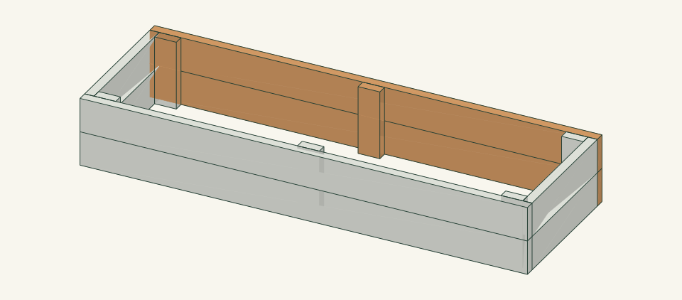
A 72 × 24 × 11-inch open-bottom cedar bed for a strip beside a fence. You tend it from the front, and the back wall can be replaced from inside the empty bed.
01 / See the shape
View the project
Loading the 3D view…
Drag to turn. Pinch or use + / − to zoom. The written step covers workholding and tool use.
Scroll or swipe the enlarged drawing to read its dimensions. Choose Fit to see the whole drawing again.
Build a Narrow Cedar Raised Bed Tended From One Side. Check the dimensions and build steps before cutting.
02 / Plan your build
Before you start
The bed is only 24 inches deep, so you reach the whole planting area from the front. The back wall sits near a boundary. Its screws are driven from inside the bed through the posts, so the back wall can be removed and replaced from the front without working in the gap behind it. The bed must stand free, with an open maintenance gap of at least 18 inches behind it. It fails if it is pushed against a fence. The fence then becomes an unplanned brace, the back wall stays wet, and nobody can inspect it. It also fails if the back screws are driven from outside, where nobody can reach them later.
Where it goes
Level native garden soil with a 24-inch standing strip along the front, 18 inches of access at each end and an 18-inch clear gap behind the back wall. Do not place it on paving, a deck or a slope, or against a fence, wall or building.
Footprint: 72 × 24 in bed. Allow a 24-in standing strip along the front, 18 in at each end and an 18-in clear gap behind the back wall, about 108 × 66 in in total
What to expect
Measure accurately, make supported square cuts and drive clamped screws to a marked pattern. Plan 5–7 hours for two people, including site layout, cutting, fastening and filling.
A planning estimate for the hands-on work, once the materials are bought and the tools are set up. It has not been timed on a finished build.
Check the spot
- A comfortable reach of at least 22.5 in from the front edge, and a 24-in standing strip in front of the bed.
- At least 18 in clear between the back face of B and any fence, wall or building, with no footing, irrigation or utility inside the 72 × 24-in outline.
- Level, drained native soil with no known contamination, major roots or slope.
Stop and check first if…
- Stop if utilities, private irrigation, major roots or past soil contamination are unresolved.
- Stop if the bed fits only by touching or leaning on the fence, or if the 18-in back gap cannot be kept.
- Stop if a screw point reaches the outside face of B, a post splits, or the screw maker's edge distances cannot be met on the 1.5-in post faces.
- Stop filling if a wall bows, a corner opens or the frame rocks. Unload the affected side before any repair.
Work safely
- Clamp the 11-in posts for cutting and drilling. Never hold a short piece beside a moving blade.
- Wear eye protection when driving the B screws from inside the frame. Keep your free hand out of the screw path behind the post.
- Carry the empty frame with two people holding both long walls. Never move it once it is filled.
Budget
We have not put a price on this one yet. Lumber and hardware prices change by store and season, so price the list under What you need at your local supplier before you buy.
03 / Gather and cut
What you need
F — Front long wall (access side)
2 pieces
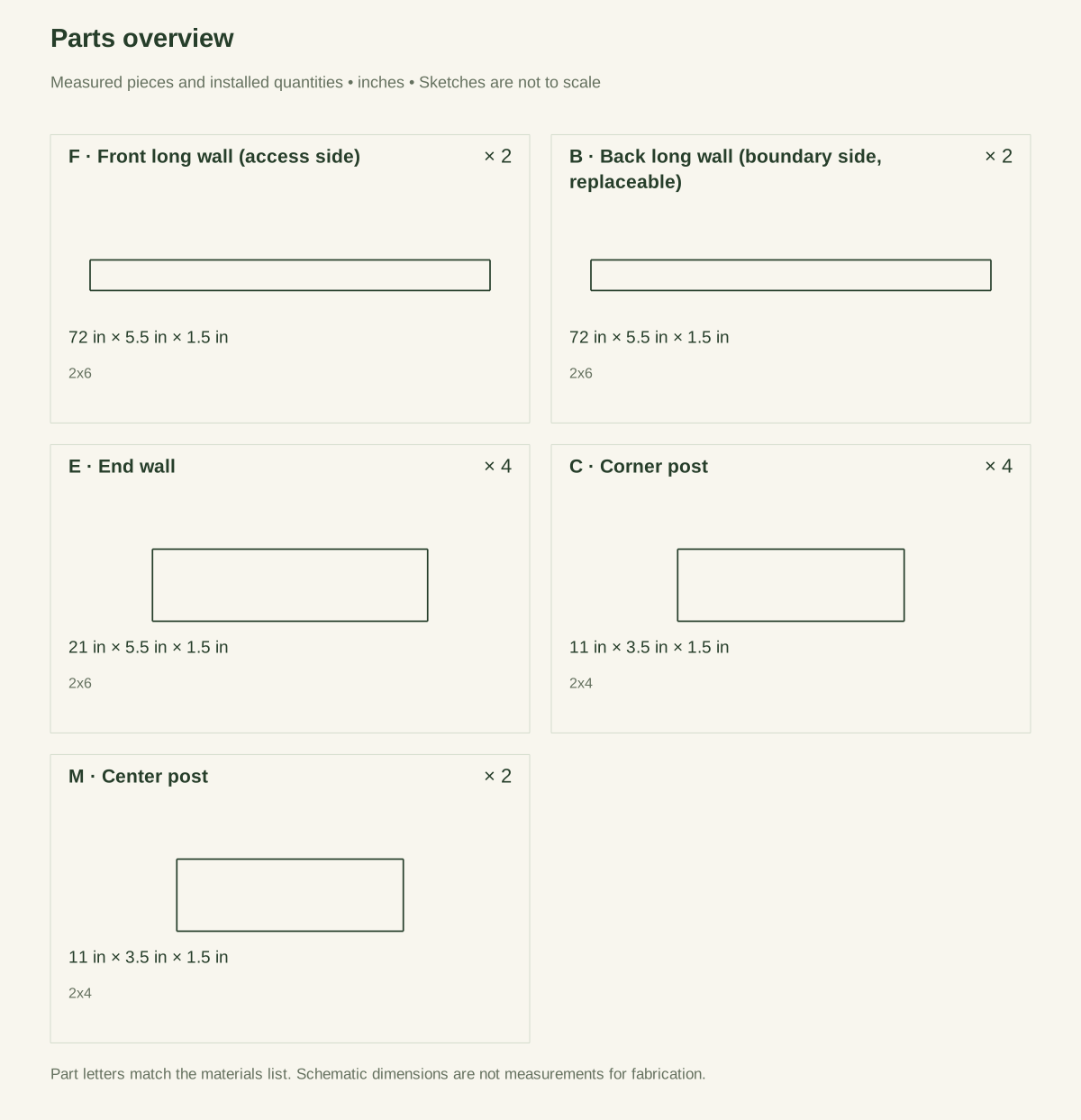
Untreated cedar 2 × 6; actual 1.5 × 5.5 in. Two 2 × 6 × 8-ft boards. Each board yields one 72-in F and one 21-in E: 72 + 21 + two 0.125-in kerfs = 93.25 of 96 in, leaving 2.75 in for end trimming.
Measure the actual section at both ends and the middle. Reject split, twisted or cupped boards. Mark the bottom edge and the outside face before cutting.
B — Back long wall (boundary side, replaceable)
2 pieces
Untreated cedar 2 × 6; actual 1.5 × 5.5 in. Two 2 × 6 × 8-ft boards. Each board yields one 72-in B and one 21-in E: 72 + 21 + two 0.125-in kerfs = 93.25 of 96 in, leaving 2.75 in for end trimming.
Label B on the inside face. B receives its screws from inside through the posts, so keep the inside face flat and free of knots where the posts bear.
E — End wall
4 pieces
Untreated cedar 2 × 6; actual 1.5 × 5.5 in. No separate purchase. Cut one E from the remainder of each of the four F and B boards.
E fits between F and B. Its length is 24 − 2 × 1.5 = 21 in. Recalculate if the measured thickness is not 1.5 in.
C — Corner post
4 pieces
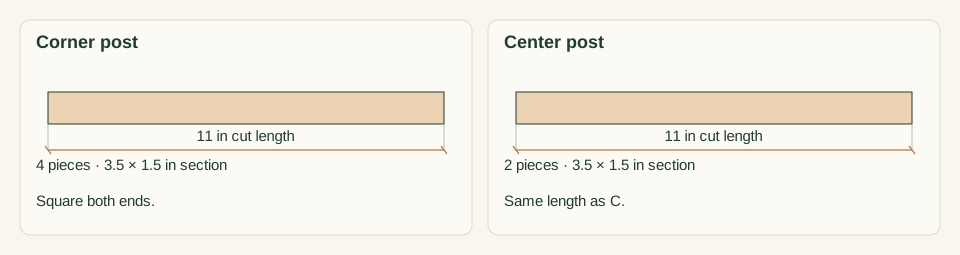
Untreated cedar 2 × 4; actual 1.5 × 3.5 in. One 2 × 4 × 8-ft board covers all four C and both M: 6 × 11 + 6 × 0.125 kerf = 66.75 of 96 in.
Cut both ends square so the post stands flush with the bottom and the rim. Reject any post with an end check near the screw positions.
M — Center post
2 pieces
Untreated cedar 2 × 4; actual 1.5 × 3.5 in. Cut from the same 2 × 4 × 8-ft board as the C posts.
M joins the two wall courses at mid-length. M is not a cross tie and does not restrain the walls against bowing.
Wall screws
40 items
#10 × 2.5 in wood screw rated by its maker for exterior use in cedar, one product throughout Buy at least 40 plus spares. Keep the spares separate from the installed count.
Front F 12, end E 16, back B 12 driven through C2, C3 and M1. Clearance hole through the driven part only; receiving pilot as the screw maker directs. No connection capacity is inferred.
Cut list
| Piece | How many | Cut length | Note |
|---|---|---|---|
| F — Front long wall (access side) | 2 | 72 × 5.5 × 1.5 in | Finished length × width × thickness; square ends unless the detail says otherwise. |
| B — Back long wall (boundary side, replaceable) | 2 | 72 × 5.5 × 1.5 in | Finished length × width × thickness; square ends unless the detail says otherwise. |
| E — End wall | 4 | 21 × 5.5 × 1.5 in | Finished length × width × thickness; square ends unless the detail says otherwise. |
| C — Corner post | 4 | 11 × 3.5 × 1.5 in | Finished length × width × thickness; square ends unless the detail says otherwise. |
| M — Center post | 2 | 11 × 3.5 × 1.5 in | Finished length × width × thickness; square ends unless the detail says otherwise. |
Tools
- Tape, combination square, pencil and a 72-in or longer straightedge
- Level, and stakes with string for the site outline
- Guarded saw suited to 2 × 6 cedar, with supported work
- Drill/driver, with the bits and depth stop specified for the selected screw
- Four or more clamps that open at least 4 in
- Abrasive paper, and a shovel or containers for the medium
Protective gear
- Eye protection during cutting and drilling
- Hearing protection and dust control matched to the actual saw
- Closed footwear, and gloves for carrying; keep gloves clear of rotating bits and blades
04 / Put it together
Build steps
- 01
Confirm reach and the boundary gap
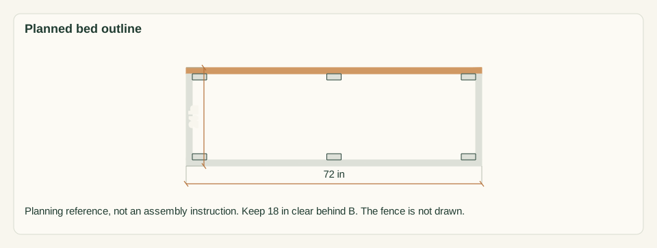
Kneel or stand where you will garden and measure your comfortable reach from the front edge. It must reach 22.5 in to the inner face of B. Mark the 72 × 24-in outline with its back edge at least 18 in from the fence or wall. Keep 18 in clear at each end and a 24-in standing strip in front. Check the site for utilities, roots and drainage.
Close-up · Whole model shows the complete part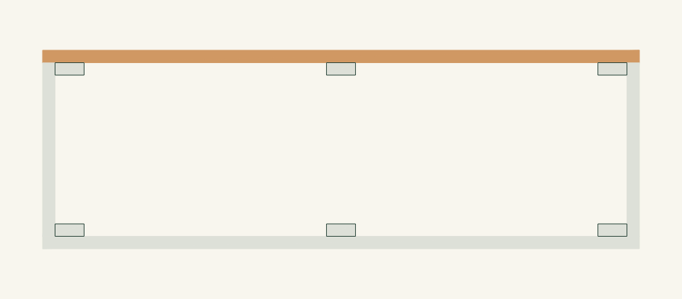
Loading the 3D view…
Drag to turn. Pinch or use + / − to zoom. The written step covers workholding and tool use.
Scroll or swipe the enlarged drawing to read its dimensions. Choose Fit to see the whole drawing again.
Planning reference only: the outline to mark, with the boundary-side wall that must stand clear of the fence.
Check: Your reach covers 22.5 in, and the 18-in back gap is clear of the fence and its footings.
- 02
Inspect and record the stock
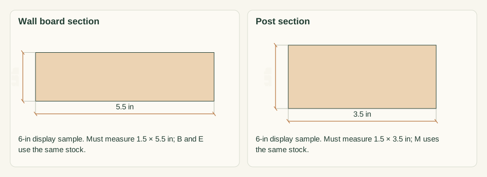
Measure each 2 × 6 board for 1.5 × 5.5 in and the 2 × 4 board for 1.5 × 3.5 in. Check both ends and the middle. Sight along each edge for twist and bow. Mark out splits, loose knots and damaged ends before planning any cut.
Close-up · Whole model shows the complete part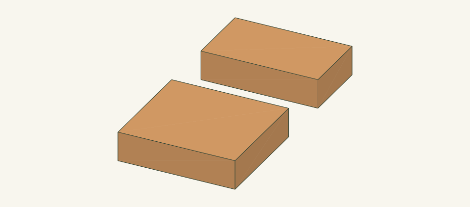
Loading the 3D view…
Drag to turn. Pinch or use + / − to zoom. The written step covers workholding and tool use.
Scroll or swipe the enlarged drawing to read its dimensions. Choose Fit to see the whole drawing again.
Measure the actual sections, not the nominal labels.
Check: Every board measures the stated section and gives at least 93.25 in or 66.75 in of sound length.
- 03
Cut the F, B and E walls
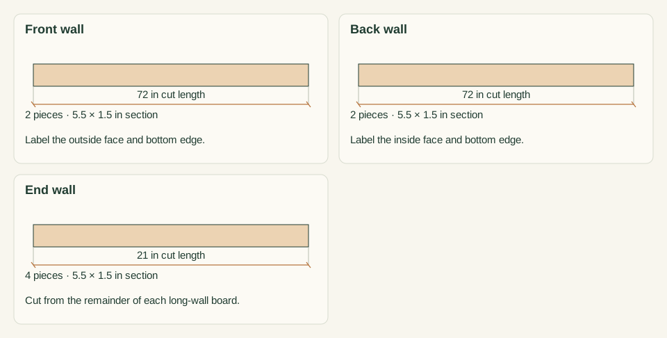
Square one datum end on each 2 × 6. On two boards, mark a 72-in F and a 21-in E. On the other two, mark a 72-in B and a 21-in E. Keep each kerf on the waste side. Support both sides of each cut. Label F, B and E, plus the bottom edge and inside face of each piece.
Close-up · Whole model shows the complete part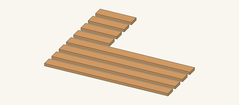
Loading the 3D view…
Drag to turn. Pinch or use + / − to zoom. The written step covers workholding and tool use.
Scroll or swipe the enlarged drawing to read its dimensions. Choose Fit to see the whole drawing again.
Each 2 × 6 gives one long wall and one end wall.
Check: Both F match, both B match and all four E match within 1/32 in.
- 04
Cut the C and M posts
Square one end of the 2 × 4. Cut six posts, each 11 in long, marking each line from a fresh square end. Clamp the board for each cut. Label four posts C and two posts M. Stand each post on a flat surface beside an F board to compare its height.
Close-up · Whole model shows the complete part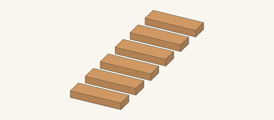
Loading the 3D view…
Drag to turn. Pinch or use + / − to zoom. The written step covers workholding and tool use.
Scroll or swipe the enlarged drawing to read its dimensions. Choose Fit to see the whole drawing again.
Six equal posts come from one 2 × 4.
Check: All six posts are 11 in long and stand square to a flat surface.
- 05
Mark the screw positions
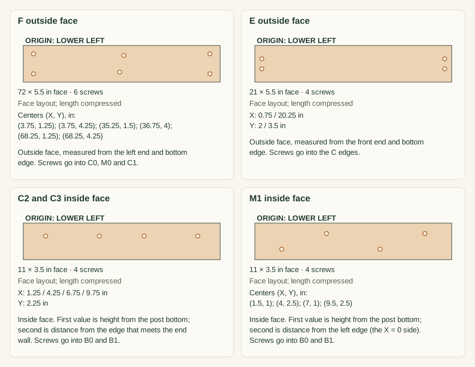
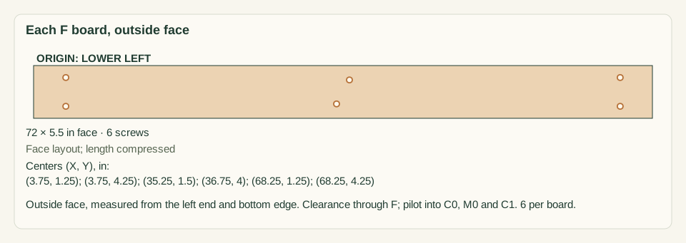
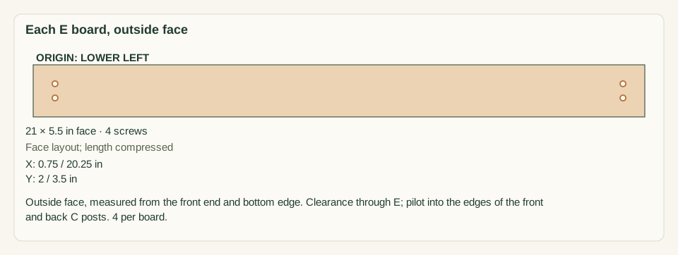
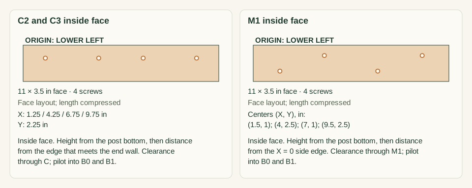
On the outside face of each F, measure from the left end and bottom edge. Mark 3.75 in and 68.25 in at 1.25 and 4.25 in high, 35.25 in at 1.5 in high and 36.75 in at 4.0 in high. On the outside face of each E, mark 0.75 and 20.25 in from the front end at 2.0 and 3.5 in high. On the inside face of C2 and C3, mark 2.25 in from the edge that meets the end wall at 1.25, 4.25, 6.75 and 9.75 in high. On the inside face of M1, mark 1.0 in from its left edge at 1.5 and 7.0 in high and 2.5 in at 4.0 and 9.5 in high.
Close-up · Whole model shows the complete part
Loading the 3D view…
Drag to turn. Pinch or use + / − to zoom. The written step covers workholding and tool use.
Scroll or swipe the enlarged drawing to read its dimensions. Choose Fit to see the whole drawing again.
Mark each pattern on the face the screw enters, measured from a named end and edge.
Check: Each F shows 6 marks, each E 4, C2 and C3 4 each and M1 4, 40 in all.
- 06
Dry-fit the lower course and posts
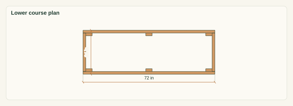
On a flat surface, stand the four C posts and two M posts. Clamp the lower F0 and B0 to the post faces, with the post bottoms flush to the board bottoms and the marked post faces facing into the bed. Fit lower E0 and E2 between F0 and B0 against the C edges. Center M at 36 in from the left end.
Close-up · Whole model shows the complete part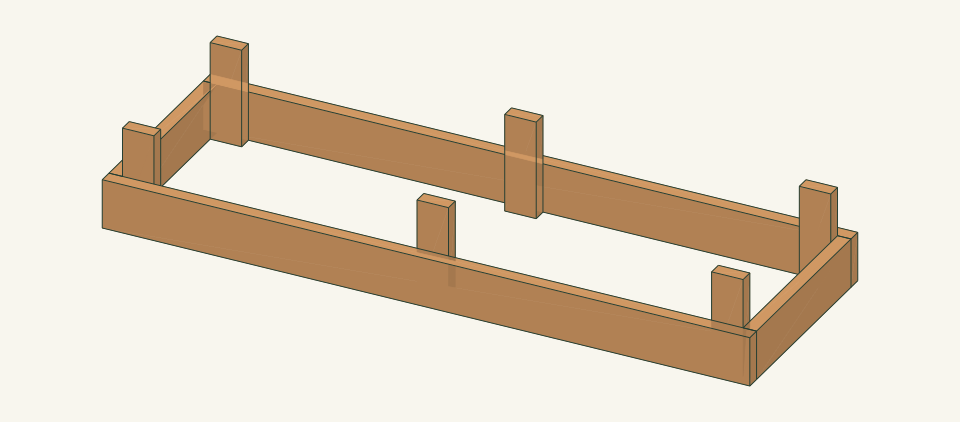
Loading the 3D view…
Drag to turn. Pinch or use + / − to zoom. The written step covers workholding and tool use.
Scroll or swipe the enlarged drawing to read its dimensions. Choose Fit to see the whole drawing again.
The long walls run through, the ends fit between, and the posts sit inside.
Check: Outside is 72 × 24 in and both diagonals measure about 75.89 in, within 1/8 in.
- 07
Add the upper course
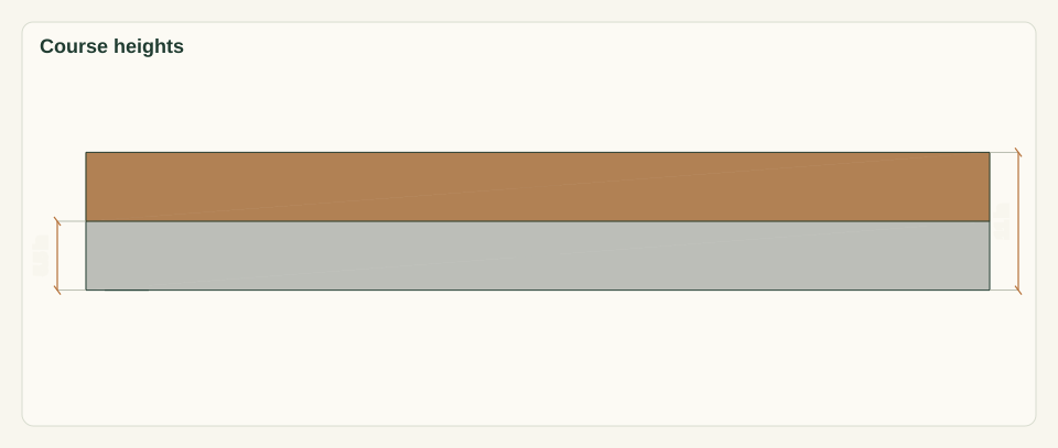
Set F1, B1, E1 and E3 on the lower course so the top edges are flush with the post tops at 11 in. Clamp each upper board to its posts. Make sure no gap opens at the course seam at 5.5 in. Recheck both diagonals.
Close-up · Whole model shows the complete part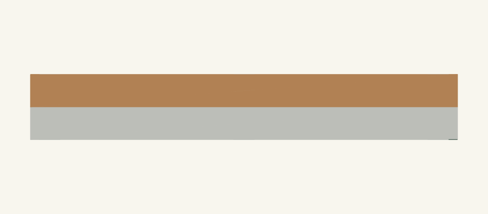
Loading the 3D view…
Drag to turn. Pinch or use + / − to zoom. The written step covers workholding and tool use.
Scroll or swipe the enlarged drawing to read its dimensions. Choose Fit to see the whole drawing again.
The second course closes the posts at the rim.
Check: The rim is level at 11 in all round and the diagonals still match.
- 08
Fasten the front walls F
With each joint clamped, drill a clearance hole through F only and a receiving pilot into the post, as the screw maker directs. Drive 6 screws through each F into C0, C1 and M0 at the marks, from the outside face, 12 in total. Seat the heads flush without crushing the cedar. Stop if a post splits.
Close-up · Whole model shows the complete part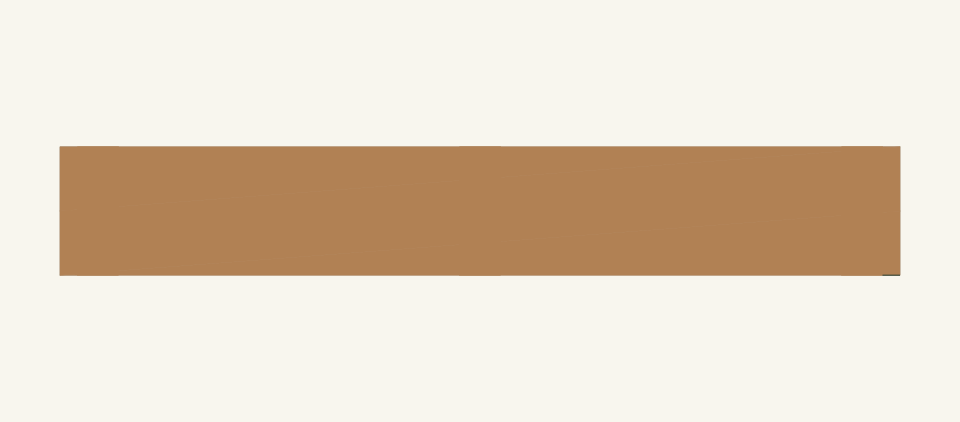
Loading the 3D view…
Drag to turn. Pinch or use + / − to zoom. The written step covers workholding and tool use.
Scroll or swipe the enlarged drawing to read its dimensions. Choose Fit to see the whole drawing again.
Front screws enter from the access side and land in the posts.
Check: All 12 F screws are seated and no screw point shows on the inside face of a post.
- 09
Fasten the end walls E
Keep the clamps on. Drive 4 screws through each E into the edges of its two corner posts at 0.75 in from each E end, at 2.0 and 3.5 in high, 16 in total. Use a clearance hole through E and a receiving pilot into the C edge. Check the frame for square after each end.
Close-up · Whole model shows the complete part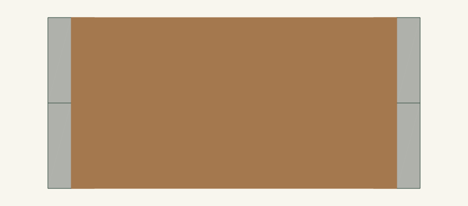
Loading the 3D view…
Drag to turn. Pinch or use + / − to zoom. The written step covers workholding and tool use.
Scroll or swipe the enlarged drawing to read its dimensions. Choose Fit to see the whole drawing again.
End screws go into the post edges at heights clear of the long-wall screws.
Check: All 16 E screws are seated and the diagonals are still within 1/8 in.
- 10
Fasten the back walls B from inside
Work from inside the frame. Drill a clearance hole through the post and a receiving pilot into B at each mark on C2, C3 and M1. Drive 4 screws through each post, 12 in total, 6 into each B board. The 2.5-in screw stops 0.5 in short of the outside face of B. Stop if a point reaches the outside face.
Close-up · Whole model shows the complete part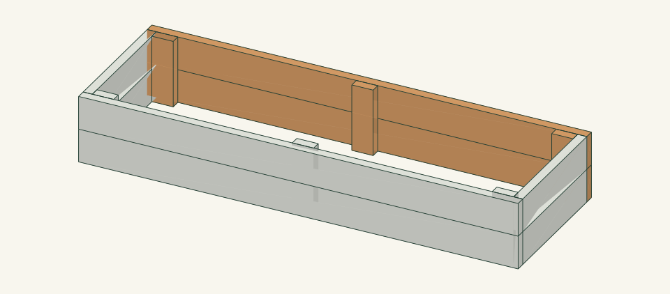
Loading the 3D view…
Drag to turn. Pinch or use + / − to zoom. The written step covers workholding and tool use.
Scroll or swipe the enlarged drawing to read its dimensions. Choose Fit to see the whole drawing again.
Back screws are driven from inside through the posts so the boundary wall can be serviced from the front.
Check: All 12 B screw heads sit on the inside post faces and no point breaks through the outside of B.
- 11
Inspect every joint before placement
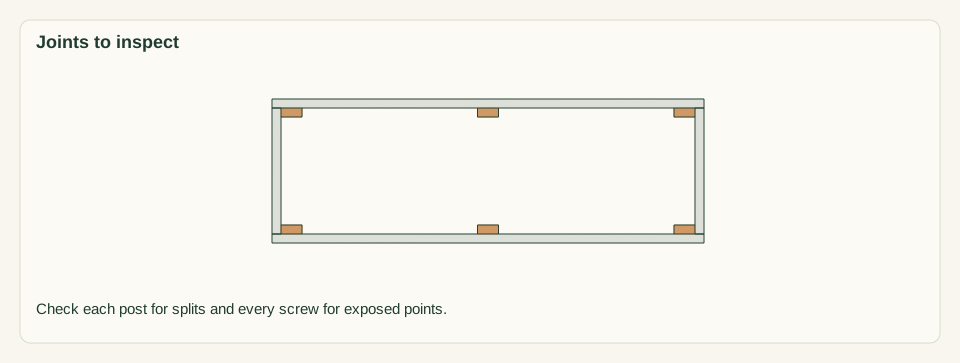
Release all clamps. Check all 40 screws for splits, stripped holes and exposed points. Confirm that every B screw head on C2, C3 and M1 can be reached from inside the bed. Ease the rim edges. Record the measured outside size and both diagonals.
Close-up · Whole model shows the complete part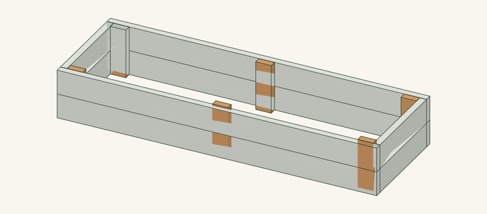
Loading the 3D view…
Drag to turn. Pinch or use + / − to zoom. The written step covers workholding and tool use.
Scroll or swipe the enlarged drawing to read its dimensions. Choose Fit to see the whole drawing again.
The posts carry every joint, so inspect them while they are still visible.
Check: The frame lies flat with no open joint, split or exposed screw point.
- 12
Place the empty frame on site
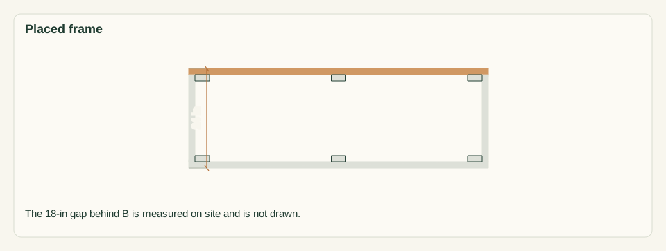
Two people carry the empty frame by both long walls. Set it on the cleared outline with F toward the standing strip. Measure at least 18 in from the back face of B to the fence at both ends and at the middle. Check that all four sides touch the soil.
Close-up · Whole model shows the complete part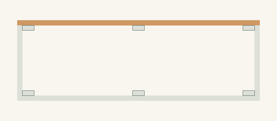
Loading the 3D view…
Drag to turn. Pinch or use + / − to zoom. The written step covers workholding and tool use.
Scroll or swipe the enlarged drawing to read its dimensions. Choose Fit to see the whole drawing again.
Orient the bed with B toward the boundary and F toward the standing strip.
Check: The frame does not rock, and the back gap is at least 18 in at all three points.
- 13
Mark the fill line and fill gradually
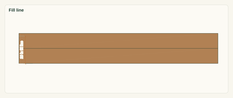
Mark 10 in above the ground on the inside faces, leaving 1 in of freeboard below the 11-in rim. Add the growing medium in shallow passes along the full 72-in length. Do not pile it against B or one end. Do not stand on the rim.
Close-up · Whole model shows the complete part
Loading the 3D view…
Drag to turn. Pinch or use + / − to zoom. The written step covers workholding and tool use.
Scroll or swipe the enlarged drawing to read its dimensions. Choose Fit to see the whole drawing again.
Fill evenly along the length so no wall takes the load alone.
Check: The fill reaches the 10-in line and no wall has moved or bowed.
- 14
Water and make the final inspection
Water as the medium and crop require. Watch how the water drains. Check B along its 72 in with a straightedge. Measure the 18-in back gap again. Recheck all four corners and both M posts for movement. Do not plant until the medium has settled.
Close-up · Whole model shows the complete partLoading the 3D view…
Drag to turn. Pinch or use + / − to zoom. The written step covers workholding and tool use.
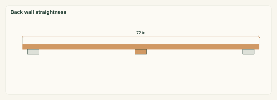
Scroll or swipe the enlarged drawing to read its dimensions. Choose Fit to see the whole drawing again.
After watering, the boundary wall is the first place to look for movement.
Check: The walls stay straight, the corners are closed and water soaks into the soil below.


05 / Keep it sound
Care
After the build
- Set the bed with F facing the open side you stand on and B facing the boundary. Do not reverse it, because the B screw heads must face into the bed.
- Plant the tallest crops along B only if they will not lean onto the fence. Choose crop spacing for a 21-in inside depth.
Check it each season
- Each season, check that B is straight, measure the 18-in back gap and inspect all 40 screws. Keep the gap free of debris, plants and stored items.
- To replace a B board, empty the bed below the bottom of that board. Remove its 6 screws from the inside faces of C2, C3 and M1. Lift B1 straight up; B0 lifts out after B1 because B sits behind the posts. Fit a new 72-in board and redrive the screws at least 0.5 in from the old holes. Have the repair reviewed if a post is damaged.
If something looks wrong
- B bows outward toward the fence
- Stop watering and unload the soil beside B. Do not wedge it against the fence. Refer the bed for review of intermediate restraint.
- Back gap has narrowed
- Measure at the ends and middle. Empty and re-site the frame. Never close the gap by leaning the bed on the boundary.
- Frame rocks before filling
- Check for high ground or debris under the walls. Level the soil rather than packing scraps under a wall.
- A B screw head is loose
- Empty the soil below that screw. Remove it and redrive it in fresh wood, or replace the board if the post is split.
- Water pools on top of the fill
- Stop watering and check the native soil and medium. Do not drill outlets in the walls toward the boundary.
Keep exploring