Wooden raised beds · Guide 30
Build a Low Raised Bed with Replaceable Panels
A low 48-inch square cedar bed with accessible corner bolts so each wall can be replaced after all soil is removed.
01 / See the shape
View the project
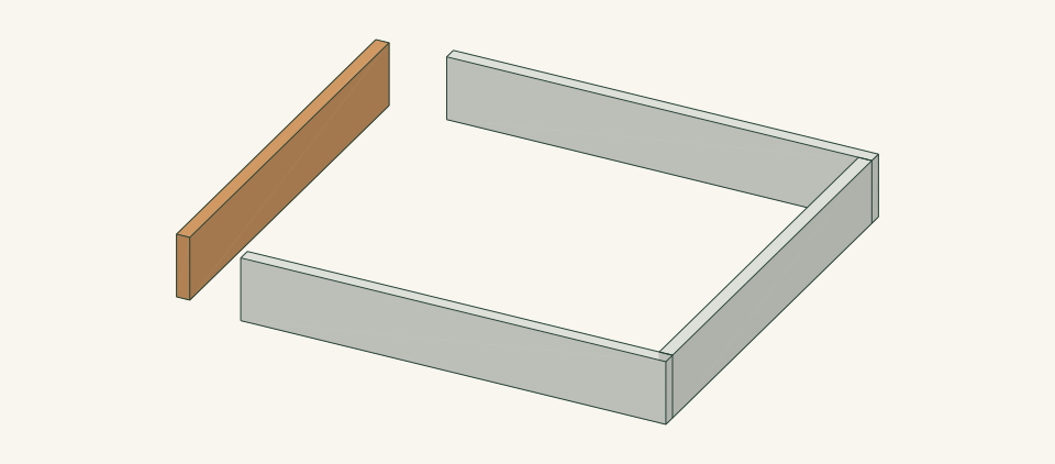
Loading the 3D view…
Drag to turn. Pinch or use + / − to zoom. The written step covers workholding and tool use.
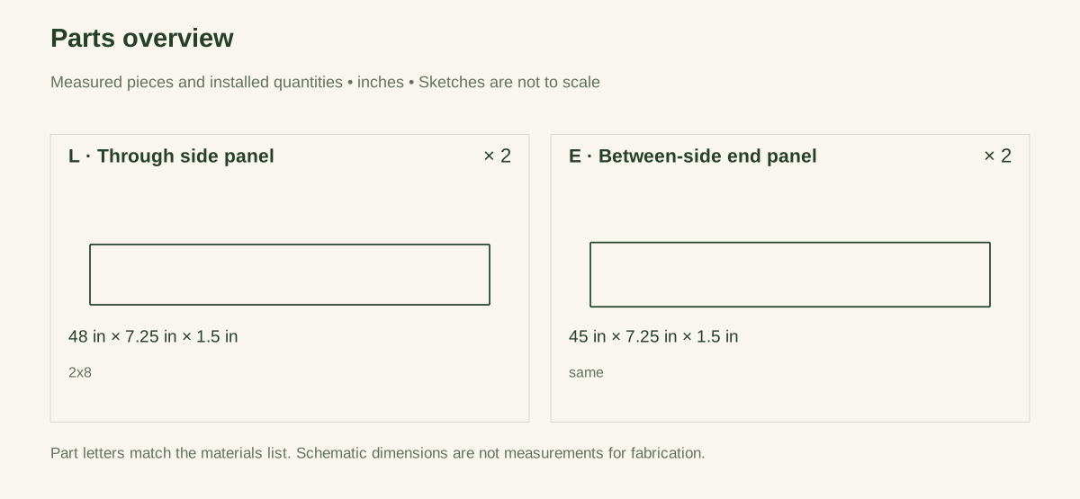
Scroll or swipe the enlarged drawing to read its dimensions. Choose Fit to see the whole drawing again.
Build a Low Raised Bed with Replaceable Panels. Check the dimensions and build steps before cutting.
02 / Plan your build
Before you start
A replaceable wall is useful only when its fixings can actually be reached. This bed uses four low cedar boards and external corner angles with through-bolts. Empty the bed before unbolting a panel; the removable joints are for repair, not for opening a loaded wall.
Where it goes
Level, suitable garden soil with reach from all four sides; not paving, a deck, a retaining edge or a building foundation.
Footprint: 48.25 × 48.25 in frame size; allow room around it to work and for anything that projects.
What to expect
Measure accurately, make supported square cuts and drill clamped joints. Plan 3–4 hours, excluding soil preparation and filling.
A planning estimate for the hands-on work, once the materials are bought and the tools are set up. It has not been timed on a finished build.
Check the spot
- Level, suitable garden soil with reach from all four sides; not paving, a deck, a retaining edge or a building foundation.
- Measure the usable stock before marking. Keep the assembly area flat and large enough to clamp the work without reaching across a moving cutter.
Stop and check first if…
- Stop if a part splits, a fixing strips, or the assembled object rocks. Unload it before opening a joint.
- Do not substitute an unknown material section or make the object taller or wider without checking every affected part and joint.
Work safely
- Have the metal fabricator deburr every angle and make its holes; do not hand-drill a loose bent bracket. Support and back each wood through-hole, and keep hands clear while two people carry the empty frame.
- Never remove a wall or corner bolt while it carries soil. Empty the entire bed before repair, support the remaining frame and keep exposed threads covered. Do not alter drainage, use the bed as retaining work or put it on a deck.
Budget
We have not put a price on this one yet. Lumber and hardware prices change by store and season, so price the list under What you need at your local supplier before you buy.
03 / Gather and cut
What you need
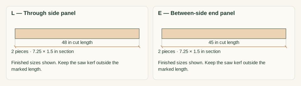
L — Through side panel
2 pieces
Untreated surfaced cedar 2 × 8; actual 1.5 × 7.25 in. Two 2 × 8 × 8-ft boards; cut one 48 and one 45 from each.
Measure your boards before cutting. Build to the finished sizes written here, not the nominal lumber label.
E — Between-side end panel
2 pieces
Same surfaced cedar as L. Included in the two wall boards.
Measure your boards before cutting. Build to the finished sizes written here, not the nominal lumber label.
A — Exterior corner angle
4 pieces
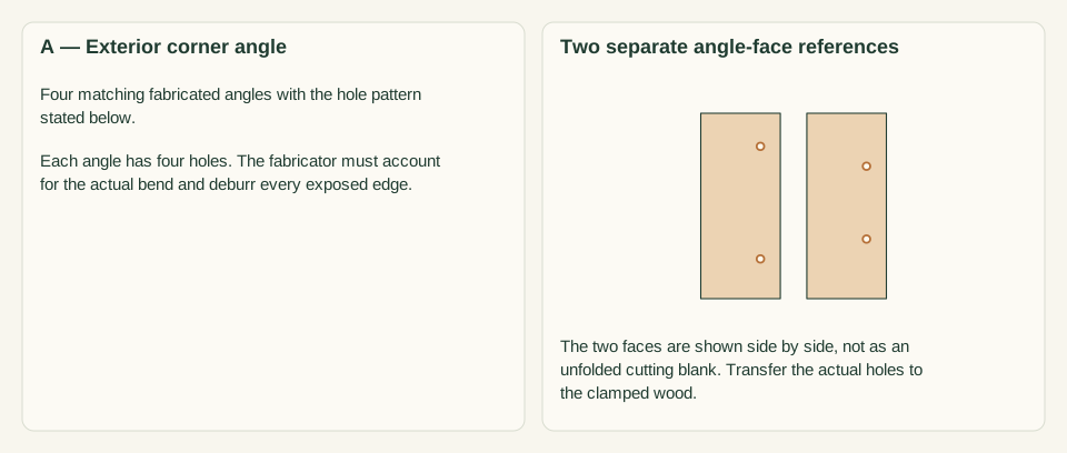
Four fabricated 316 stainless corner angles, each 7 inches high with 3 × 3-inch outside legs and 0.125-inch stock thickness. A competent metal fabricator makes the hole pattern. Four matching fabricated angles with the hole pattern stated below.
All cut edges deburred and corners rounded; no protruding sharp top edge.
Panel bolts
16 items
1/4-20 × 2-1/4 in 316 stainless bolts Buy 16 matching 1/4-20 × 2.25-inch bolts; keep spares separate.
Length is measured below the head. Check the actual bracket, wood, washers and locknut stack on one corner before drilling the other panels.
Washers
32 items
32 stainless 1/4-inch flat washers, each no thicker than 1/16 inch Buy 32 washers, one under each bolt head and one under each nut.
Use flat washers wide enough to avoid crushing the cedar, compatible with the chosen bolts and corner holes.
Locknuts
16 items
Sixteen 1/4-20 stainless prevailing-torque locknuts, overall height at most 0.375 inch Buy 16 matching nuts with the bolt maker’s compatible anti-galling treatment if required.
Use an anti-galling method compatible with the chosen stainless hardware; no lubricant contacts growing media.
Thread-end covers
16 items
Sixteen smooth moisture-resistant caps compatible with the exposed bolt ends Buy 16 caps that fit the actual assembled thread projection.
Fit only after confirming full locking-nut engagement; caps are not substitutes for locknuts.
Cut list
| Piece | How many | Cut length | Note |
|---|---|---|---|
| L — Through side panel | 2 | 48 × 7.25 × 1.5 in | Finished length × width × thickness; square ends unless the detail says otherwise. |
| E — Between-side end panel | 2 | 45 × 7.25 × 1.5 in | Finished length × width × thickness; square ends unless the detail says otherwise. |
Tools
- Tape or rule, square and sharp pencil
- Clamps, a flat bench and sacrificial backing
- Suitable guarded saw for the specified stock
- Drill, 9/32-inch clearance bit, perpendicular drilling guide and backing for the wood panels
- Fine abrasive and a dust brush
- 9/32-inch drill bit and backing; two hand wrenches matched to the bolt heads and nuts; pencil for the fill line
Protective gear
- Eye protection during cutting and drilling
- Hearing protection and dust collection appropriate to the actual tools
- Closed footwear; keep loose clothing and gloves away from rotating cutters
04 / Put it together
Build steps
- 01
Select the site and verify reach
Mark a 48.25-inch square on suitable level soil. Walk all four sides with the intended tools. Resolve utilities before disturbing the ground and reject ponding, major roots or a retaining condition.
Close-up · Whole model shows the complete part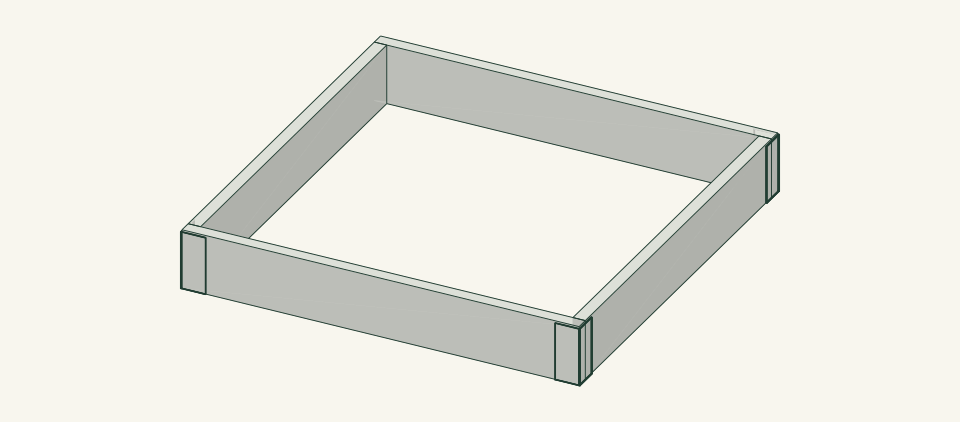
Loading the 3D view…
Drag to turn. Pinch or use + / − to zoom. The written step covers workholding and tool use.
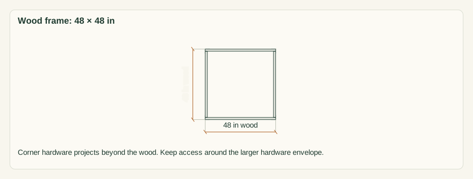
Scroll or swipe the enlarged drawing to read its dimensions. Choose Fit to see the whole drawing again.
Check all-side access and ground bearing using the finished frame as a footprint reference.
Check: The empty frame can sit flat without changing site drainage.
- 02
Order and check the corner angles
Give the hole schedule to the metal fabricator. Ask for deburred edges and rounded exposed corners. Check one angle against two clamped wall offcuts before accepting the set. Each bolt passes through the angle and ONE wall, with two washers and full locknut engagement. It does not pass through both boards at once.
Close-up · Whole model shows the complete part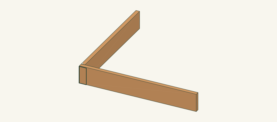
Loading the 3D view…
Drag to turn. Pinch or use + / − to zoom. The written step covers workholding and tool use.
Scroll or swipe the enlarged drawing to read its dimensions. Choose Fit to see the whole drawing again.
Check a real fabricated angle against clamped wall offcuts before accepting the full set. The thin outlines are only its fitting envelope.
Check: Every angle has four matching holes and can be handled without catching a cloth.
- 03
Cut the four cedar panels
Measure the actual 1.5-inch thickness. Cut one 48-inch L and one 45-inch E from each 8-foot board, keeping kerf on the waste side. Label the inside face and bottom edge.
Close-up · Whole model shows the complete part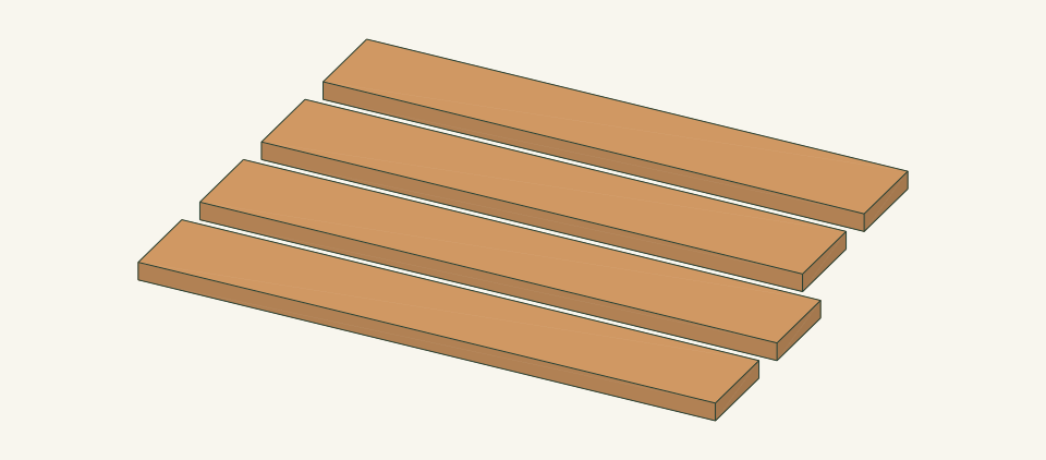
Loading the 3D view…
Drag to turn. Pinch or use + / − to zoom. The written step covers workholding and tool use.
Scroll or swipe the enlarged drawing to read its dimensions. Choose Fit to see the whole drawing again.
Cut two long panels and two shorter end panels. The end pieces fit between the long sides.
Check: Two long panels match; two end panels match; all ends are square.
- 04
Clamp the bare wood rectangle
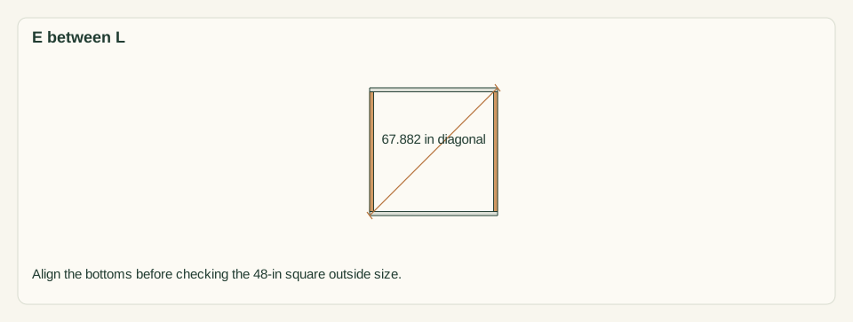
Place E between L on a flat surface with the four bottoms aligned. Clamp without bowing. Measure 48 inches across each outside dimension and compare the two 67.882-inch design diagonals.
Close-up · Whole model shows the complete part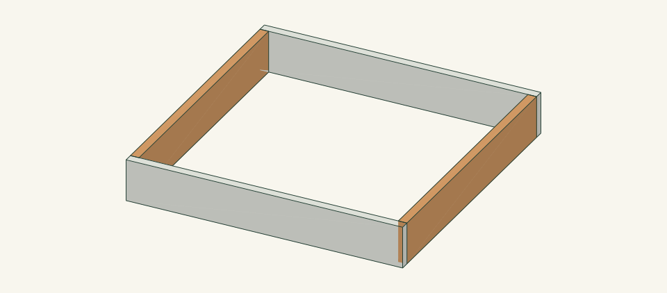
Loading the 3D view…
Drag to turn. Pinch or use + / − to zoom. The written step covers workholding and tool use.
Scroll or swipe the enlarged drawing to read its dimensions. Choose Fit to see the whole drawing again.
Clamp the bare wood rectangle with the ends between the long panels. Hardware is not installed at this stage.
Check: Diagonal difference is at most 1/8 inch as a shop-layout target.
- 05
Transfer the real angle hole positions
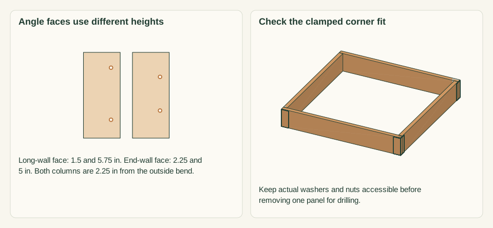
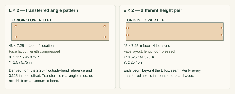
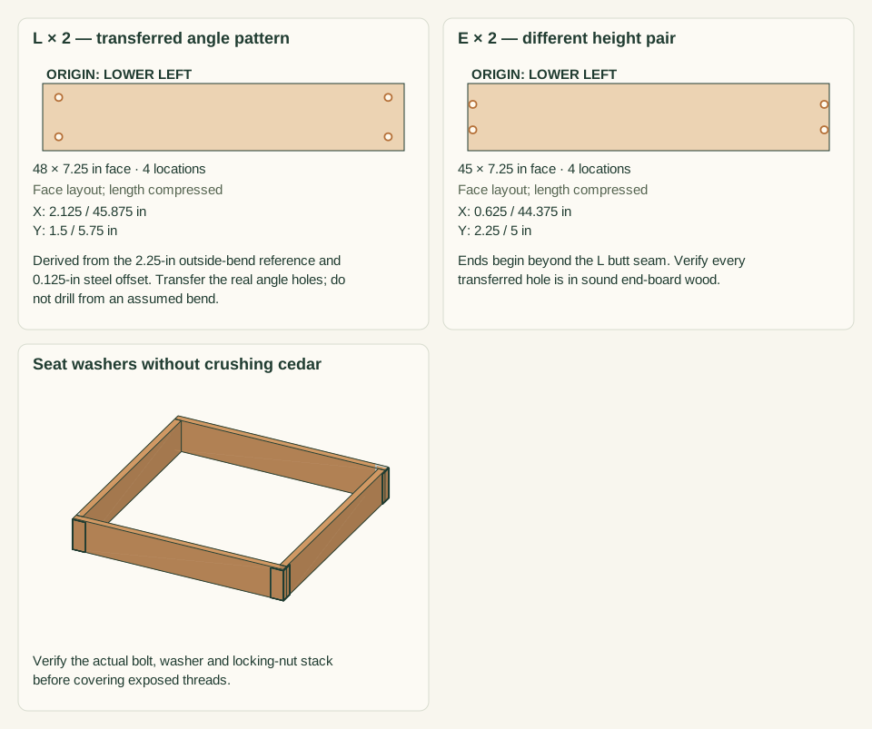
Fit each real angle outside its clamped corner, with its bottom flush with the wood bottom and its top 0.25 inch below the rim. On the long-wall face use heights 1.5 and 5.75 inches; on the perpendicular end-wall face use 2.25 and 5 inches. Each hole column is 2.25 inches from the angle outside bend corner. Transfer the fabricated holes, checking every end-board hole lies beyond the butt seam in solid wood.
Close-up · Whole model shows the complete part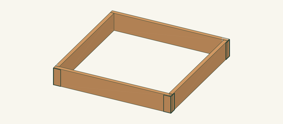
Loading the 3D view…
Drag to turn. Pinch or use + / − to zoom. The written step covers workholding and tool use.
Scroll or swipe the enlarged drawing to read its dimensions. Choose Fit to see the whole drawing again.
Fit and label the four angle pairs, then transfer their holes. Long-wall and end-wall hole heights are intentionally different.
Check: Every proposed hole is inside solid wood and matches its angle.
- 06
Drill clearance holes with backing
Label each corner pair. Remove one panel at a time, clamp it over sacrificial backing and drill 9/32-inch through holes perpendicular to the face. Deburr the wood without widening the holes.
Close-up · Whole model shows the complete part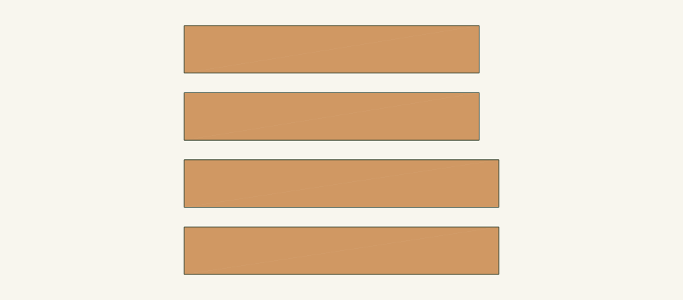
Loading the 3D view…
Drag to turn. Pinch or use + / − to zoom. The written step covers workholding and tool use.
Scroll or swipe the enlarged drawing to read its dimensions. Choose Fit to see the whole drawing again.
Remove and support one labeled panel at a time to drill the sixteen transferred clearance holes.
Check: A 1/4-inch bolt passes freely without hammering or a ragged exit.
- 07
Bolt the corners without crushing cedar
Reassemble square with one washer under each bolt head and nut. With 0.125-inch steel, 1.5-inch wood and two 1/16-inch washers, 0.5 inch of the 2.25-inch bolt remains for the nut and exposed thread. Use the selected nut at most 0.375 inch high and verify its locking feature is fully engaged. Tighten slowly by hand using the specified anti-galling method, shield growing media from any treatment, and fit smooth thread-end covers. Stop before crushing cedar.
Close-up · Whole model shows the complete part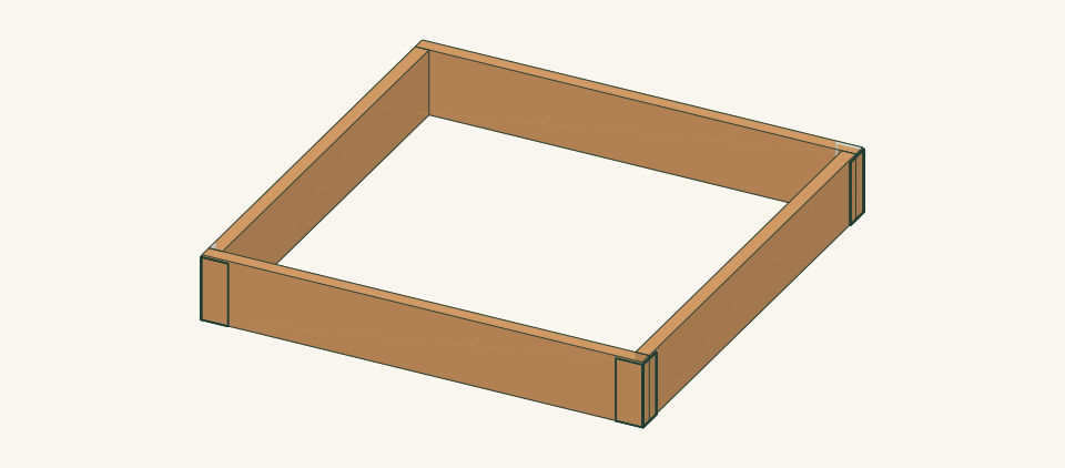
Loading the 3D view…
Drag to turn. Pinch or use + / − to zoom. The written step covers workholding and tool use.
Scroll or swipe the enlarged drawing to read its dimensions. Choose Fit to see the whole drawing again.
Reassemble with the actual angles and sixteen through-bolts. The location symbols are transferred centers, not bolt-head or drill diameters.
Check: All 16 bolts are present; no split or deeply crushed washer seat appears.
- 08
Position and inspect the empty bed
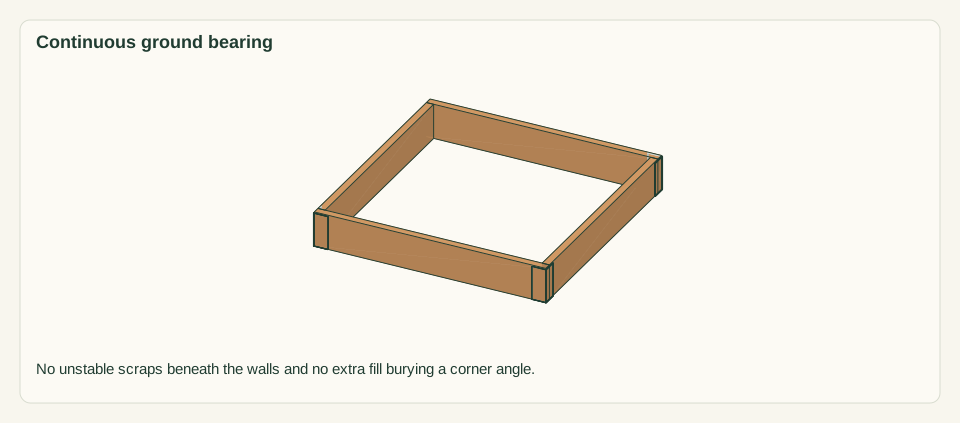
With assistance, carry the empty frame to its marked ground position. Check that each wall bears continuously and that all nuts remain accessible. Do not level it with unstable scraps or bury a corner angle in extra fill.
Close-up · Whole model shows the complete part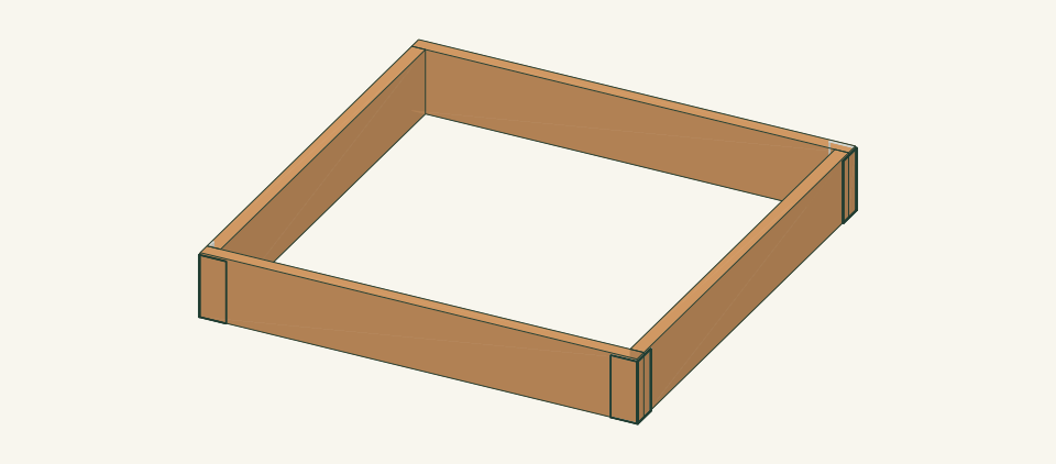
Loading the 3D view…
Drag to turn. Pinch or use + / − to zoom. The written step covers workholding and tool use.
Scroll or swipe the enlarged drawing to read its dimensions. Choose Fit to see the whole drawing again.
Carry the empty bed to the checked soil and retain access to every corner fixing.
Check: The empty assembly is flat, square and accessible on all four sides.
- 09
Mark the fill line and add growing medium
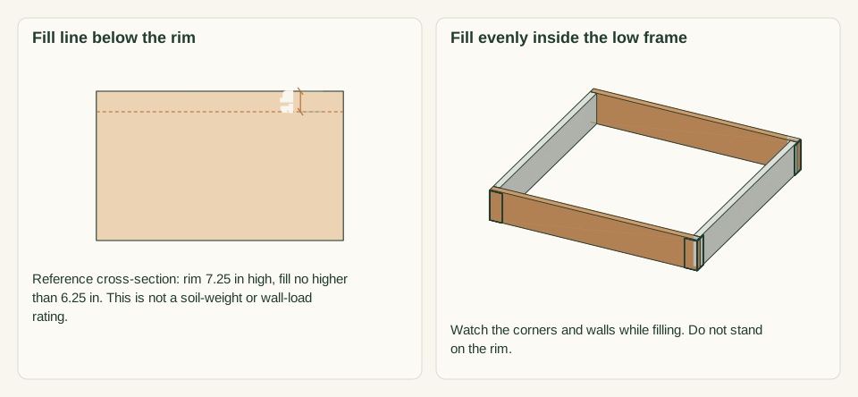
Mark a line 6.25 inches above ground. The modeled inside volume is 45 × 45 × 6.25 / 1728 = 7.324 cubic feet; external angles do not displace this soil. Add medium evenly without standing on the rim.
Close-up · Whole model shows the complete part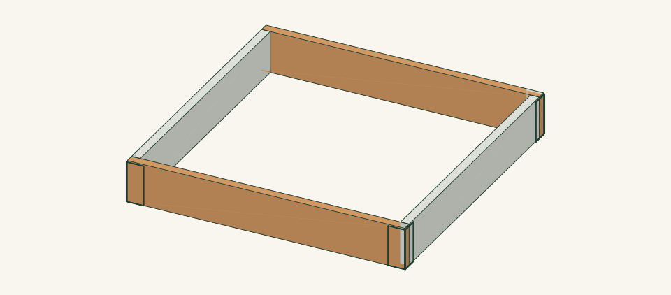
Loading the 3D view…
Drag to turn. Pinch or use + / − to zoom. The written step covers workholding and tool use.
Scroll or swipe the enlarged drawing to read its dimensions. Choose Fit to see the whole drawing again.
Mark the 6.25-in fill line before adding medium. Keep the one-inch freeboard visible.
Check: Freeboard stays at least one inch and no joint moves while filling.
- 10
Rehearse the replacement sequence
Before filling or planting, note which bolts release each panel. For any future repair, remove ALL soil from the entire bed and support the remaining empty frame before unbolting a panel. Fit the identical wall section, then repeat the squareness, corner and empty-frame inspections before refilling.
Close-up · Whole model shows the complete partLoading the 3D view…
Drag to turn. Pinch or use + / − to zoom. The written step covers workholding and tool use.
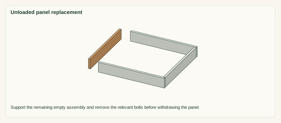
Scroll or swipe the enlarged drawing to read its dimensions. Choose Fit to see the whole drawing again.
Remove all soil before releasing any panel. The displaced E panel illustrates an unloaded repair, not an opening in a loaded bed.
Check: No instruction permits removing a wall while it is carrying soil.


05 / Keep it sound
Care
After the build
- Choose plants for actual light, reach and usable root depth below the open frame. Water gently and inspect settlement before topping up.
- Use the volume as an ordering calculation, not a wet-weight or wall-load rating. Obtain medium density separately where a weight is needed.
Check it each season
- Inspect bolts, caps and wood corners before planting and after wet weather. Empty the whole bed before opening, tightening or replacing a joint; replace split wood rather than adding a nearby hole.
- Keep outside bolt access clear of soil and vegetation. Remove standing water at the site without raising soil against a wall or changing the planned drainage.
If something looks wrong
- An angle will not seat
- Stop and compare the hole pattern and actual thickness. Do not pull a mismatched panel into place with the bolts.
- Washer sinks into cedar
- Back off, unload the joint and replace crushed material; hand-tighten only to a seated connection.
- A panel bows during filling
- Stop, unload that side and resolve the connection/design before continuing.
- Bolts cannot be removed for repair
- Clear the soil and working access first; do not pry against a loaded adjacent panel.
Keep exploring