Wooden raised beds · Guide 31
Build a Level Timber Raised Bed on a Mild Slope
Build a 48 × 36-inch timber bed that sits level on a shallow cut bench, on ground falling no more than 2 inches, without building up fill under the downhill wall.
01 / See the shape
View the project
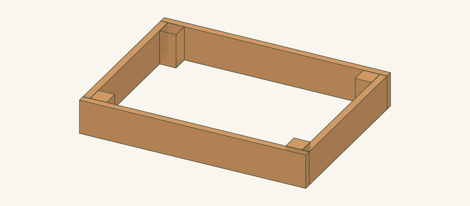
Loading the 3D view…
Drag to turn. Pinch or use + / − to zoom. The written step covers workholding and tool use.

Scroll or swipe the enlarged drawing to read its dimensions. Choose Fit to see the whole drawing again.
Final overview of the level frame on the bench, ready for planting.
02 / Plan your build
Before you start
This bed stays level on a mild slope because the ground under it is cut down to a level bench. The ground is never built up. The downhill front wall bears on undisturbed soil at existing grade. The uphill side is lowered by no more than 2 inches. A 4-inch drained strip separates the back wall from the small cut face. The walls hold the same 6.25-inch fill depth they would hold on flat ground, so no wall acts as a retaining wall. The common failure is to block up or raise the downhill side to reach level. That wall then holds extra soil and loose fill beneath it, and it can bow, settle or slide. The second failure is a bench that traps runoff against the back wall. Do not use this guide where the measured fall exceeds 2 inches across the 36-inch depth. OSU Extension discusses bed width, site selection and access. It does not approve this slope detail or the corner connection.
Where it goes
Use a stable, mild slope with no more than 2 inches of fall across the 36-inch bed depth, with the 48-inch length along the contour and at least 24 inches of access all round. Do not build against a building, at the top of a bank or wall, on fill, on paving or in a runoff channel.
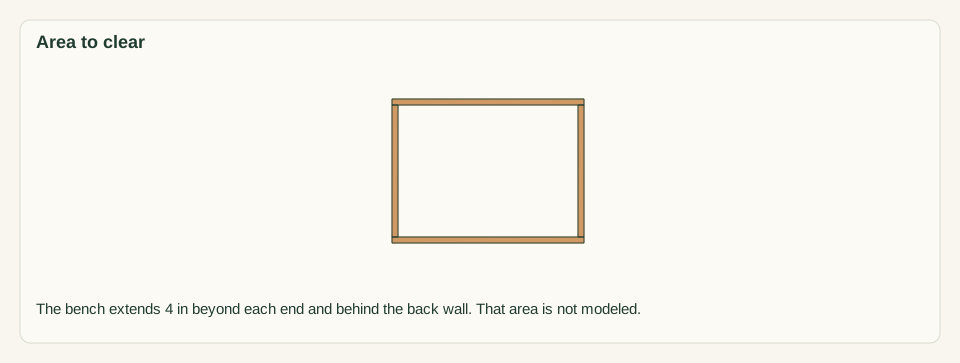
Footprint: The frame is 48 × 36 in. It sits on a 56 × 40-in level bench that extends 4 in beyond each end and 4 in behind the back wall. Allow at least 24 in of working access on all sides, outside the bench and its cut face
What to expect
Measure and level accurately, make supported square cuts, drill clamped joints and shape soil by hand. Plan 5–7 hours including the slope survey, bench cutting and a runoff test. Waiting time for utility location is not included.
A planning estimate for the hands-on work, once the materials are bought and the tools are set up. It has not been timed on a finished build.
Check the spot
- Measured fall of 2 in or less across the 36-in depth, with the 48-in length along the contour.
- Utilities, private irrigation, drain lines and major roots identified before digging.
- No concentrated runoff, seep, recent fill or unstable soil within the 56 × 40-in bench.
- At least 24 in of access on all sides, and no building, wall edge or bank top nearby.
Stop and check first if…
- Stop if the fall exceeds 2 in, if reaching level would need fill under any wall, or if the cut would exceed 2 in.
- Stop if utilities, roots, contamination history or soil stability are unknown.
- Stop if runoff ponds against the back wall or scours under the front wall. Do not fill until this is resolved.
- Stop if a post splits, a screw strips, a corner opens or a wall bows during filling. Unload the soil before repair.
Work safely
- Clamp the stock and keep the saw guard working. Cut the short C posts from a long clamped piece, never from a hand-held block.
- Dig only after utility location. Use hand tools near any marked line and stop at any unexpected pipe, cable or tape.
- Lift the frame with two people, supported under both long walls. Never move it after filling.
Budget
We have not put a price on this one yet. Lumber and hardware prices change by store and season, so price the list under What you need at your local supplier before you buy.
03 / Gather and cut
What you need
L — Long wall (front downhill and back uphill), runs through
2 pieces
Cedar or redwood 2 × 8; actual 1.5 × 7.25 in. A reviewer confirms species, grade and suitability for edible growing. Two 2 × 8 × 8-ft boards, which are shared with part E. Each board yields one L and one E: 1-in square-up trim + 48 + 0.125 kerf + 33 + 0.125 kerf = 82.25 in. This leaves 13.75 in of each 96-in board as offcut.
Measure the actual thickness and width at both ends and in the middle before cutting. Reject boards with splits, through-knots near the ends or more than 1/8 in of twist over 48 in.
E — End wall, fits between the long walls
2 pieces
Same cedar or redwood 2 × 8 as part L; actual 1.5 × 7.25 in. Cut from the same two 2 × 8 × 8-ft boards as part L. See the L arithmetic.
The 33-in length assumes L is exactly 1.5 in thick. If the measured thickness differs, stop and reconcile the outside depth before cutting.
C — Corner post
4 pieces
Cedar or redwood 4 × 4; actual 3.5 × 3.5 in. One 4 × 4 stock length with at least 30.5 in of sound usable wood: 1-in trim + 4 × 7.25 + 4 × 0.125 kerf = 30.5 in.
Check that each post is square in section and free of end checks. Cut the post length to the measured wall width if it is not exactly 7.25 in.
Corner screws
16 items
#10 × 3 in exterior wood screws, stainless steel or a coated screw that its maker lists for outdoor use with the chosen species Buy at least 16 plus spares for trial holes. Keep spares separate from the installed count.
4 corners × 2 wall faces × 2 screws. Each screw passes through 1.5 in of wall and engages 1.5 in of post. Follow the maker's pilot and clearance instructions. No connection capacity is assigned.
Cut list
| Piece | How many | Cut length | Note |
|---|---|---|---|
| L — Long wall (front downhill and back uphill), runs through | 2 | 48 × 7.25 × 1.5 in | Square both ends. The 48-in length is the outside frame length. |
| E — End wall, fits between the long walls | 2 | 33 × 7.25 × 1.5 in | Square both ends. 33 + 2 × 1.5 = 36 in outside depth. |
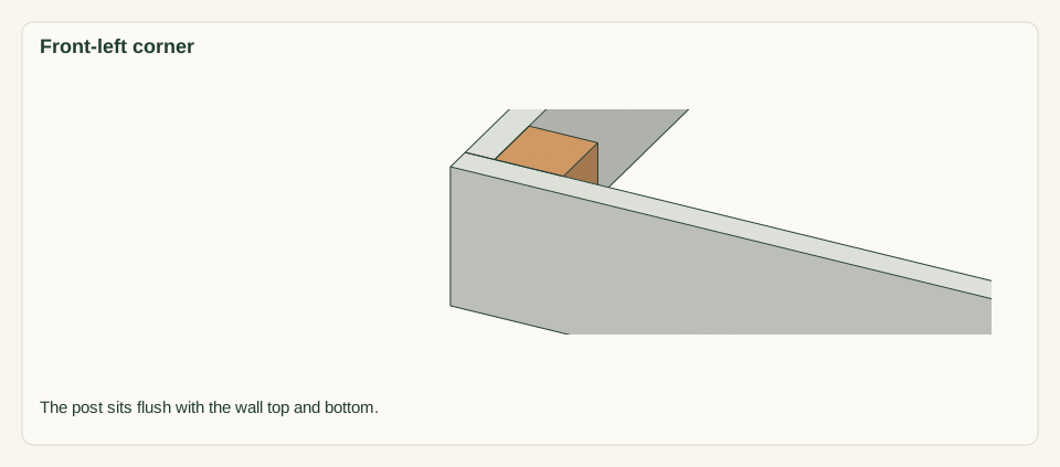
| C — Corner post | 4 | 7.25 × 3.5 × 3.5 in | Square both ends. The length equals the wall height, so the posts sit flush at top and bottom. |
Tools
- Tape, framing square, pencil, string line and four stakes
- Straight board at least 48 in long and a level
- Guarded saw suited to 2 × 8 and 4 × 4 stock, with clamps and supported work
- Drill/driver and the bits specified by the screw maker
- Hand spade, flat shovel and rake for the bench
- Garden hose for the runoff test
- Abrasive paper
Protective gear
- Eye protection during cutting, drilling and digging
- Hearing and dust protection matched to the actual saw and wood
- Closed footwear and work gloves for soil and lumber handling. Keep gloves away from rotating cutters.
04 / Put it together
Build steps
- 01
Survey the cross-slope
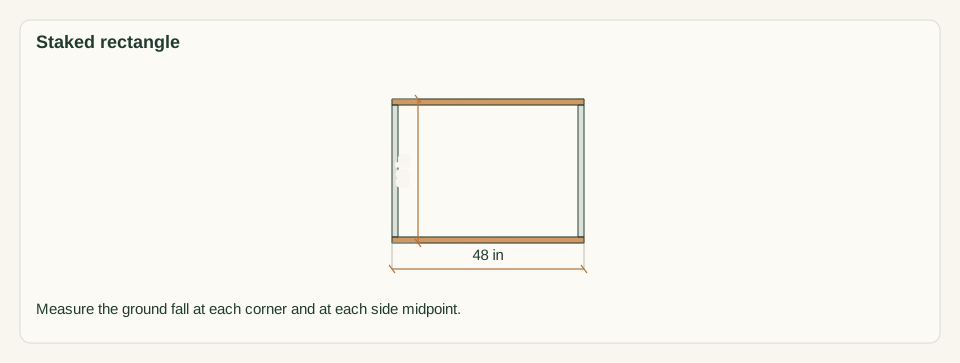
Stake a 48 × 36-inch rectangle with the 48-inch sides along the contour and the front edge downhill. Hold a straight board and level from the highest stake. Measure down to the ground at all four corners and at the midpoint of each side. Record every reading. The fall is the difference between the highest and lowest ground point inside the rectangle.
Close-up · Whole model shows the complete part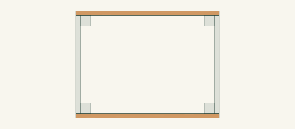
Loading the 3D view…
Drag to turn. Pinch or use + / − to zoom. The written step covers workholding and tool use.
Scroll or swipe the enlarged drawing to read its dimensions. Choose Fit to see the whole drawing again.
Planning reference only. The 48-inch length runs along the contour, with the front wall downhill.
Check: The recorded fall is 2 inches or less at every point. Stop and refer the site if it is more.
- 02
Clear utilities and read the runoff
Complete the current utility-location procedure before any digging. Also identify private irrigation, drain lines and major roots inside a 56 × 40-inch bench area. Watch the site in rain or run a low-flow hose uphill. Note where water travels and confirm that it does not concentrate across the staked rectangle.
Close-up · Whole model shows the complete part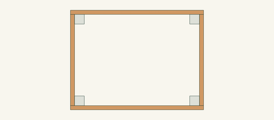
Loading the 3D view…
Drag to turn. Pinch or use + / − to zoom. The written step covers workholding and tool use.
Scroll or swipe the enlarged drawing to read its dimensions. Choose Fit to see the whole drawing again.
Planning reference for checking utilities and runoff across the future bench area.
Check: Utilities are marked or confirmed clear, and no gully, seep or concentrated flow crosses the bench area.
- 03
Check and record the stock
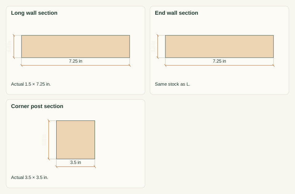
Measure both 2 × 8 boards for parts L and E at both ends and in the middle. They must be 1.5 × 7.25 inches. Measure the 4 × 4 for part C at 3.5 × 3.5 inches. Mark split ends and defects. Confirm 82.25 inches of usable length per board and 30.5 inches on the post stock.
Close-up · Whole model shows the complete part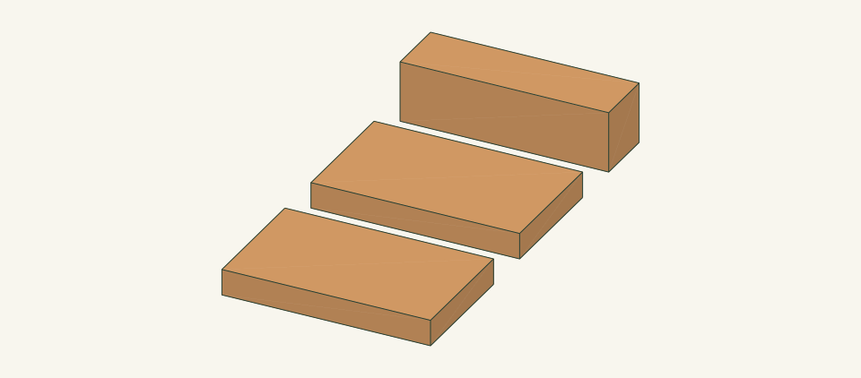
Loading the 3D view…
Drag to turn. Pinch or use + / − to zoom. The written step covers workholding and tool use.
Scroll or swipe the enlarged drawing to read its dimensions. Choose Fit to see the whole drawing again.
Compare the measured sections with the cut list before marking any stock.
Check: Measured sections match 1.5 × 7.25 and 3.5 × 3.5 inches, with enough sound length for every part.
- 04
Cut the walls L and E
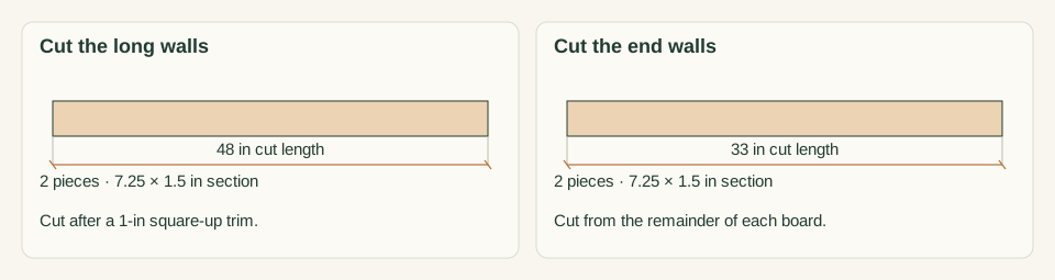
Clamp and support each 2 × 8 board. Square one end with a 1-inch trim. Mark and cut one 48-inch L, then one 33-inch E, keeping the kerf on the waste side. Repeat on the second board. Label the outside face and bottom edge of every wall. Mark one L as the downhill front wall.
Close-up · Whole model shows the complete part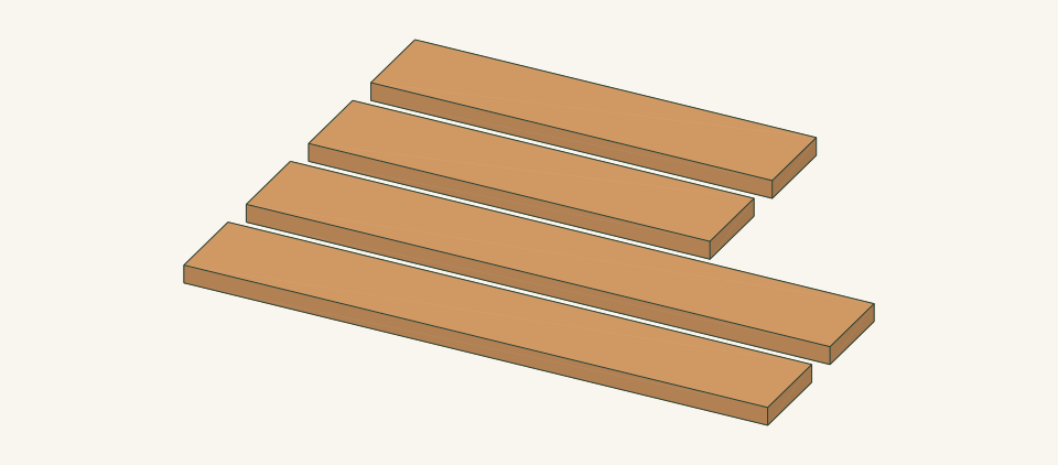
Loading the 3D view…
Drag to turn. Pinch or use + / − to zoom. The written step covers workholding and tool use.
Scroll or swipe the enlarged drawing to read its dimensions. Choose Fit to see the whole drawing again.
Each board yields one long wall and one end wall.
Check: The two L parts match at 48 inches and the two E parts match at 33 inches, with square ends.
- 05
Cut the four corner posts C
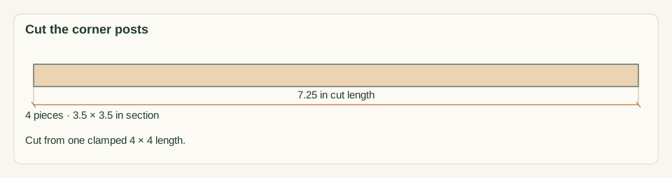
Clamp the 4 × 4 stock and square one end. Cut four C posts at 7.25 inches, or at the measured wall width if it differs. Never hold a short offcut beside the blade. Stand each post on edge against an E wall to check that the post and wall are the same height.
Close-up · Whole model shows the complete part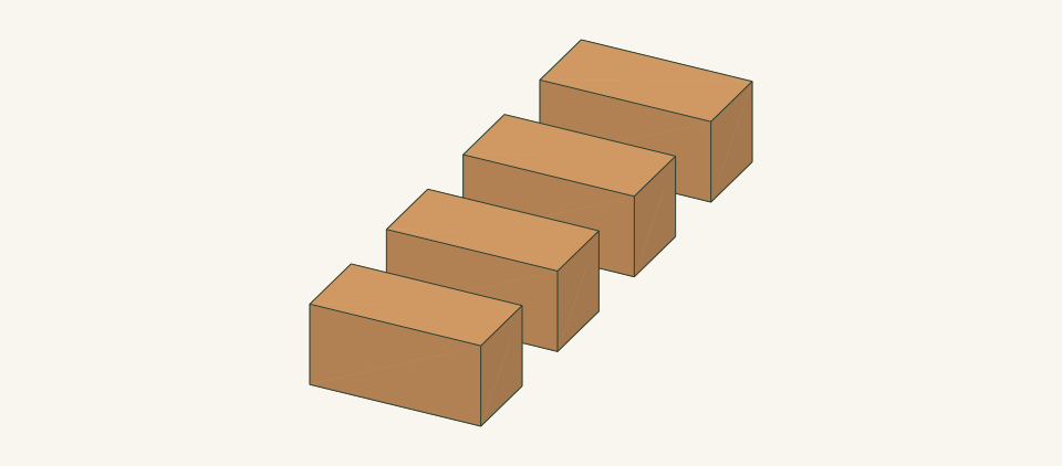
Loading the 3D view…
Drag to turn. Pinch or use + / − to zoom. The written step covers workholding and tool use.
Scroll or swipe the enlarged drawing to read its dimensions. Choose Fit to see the whole drawing again.
The posts are cut to the wall height so they sit flush top and bottom.
Check: Four posts are cut square and sit flush with the wall top and bottom edges.
- 06
Mark the corner screw pattern
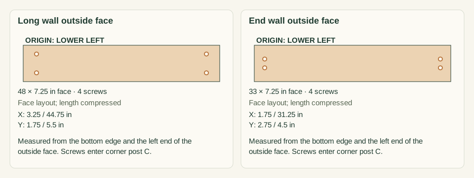
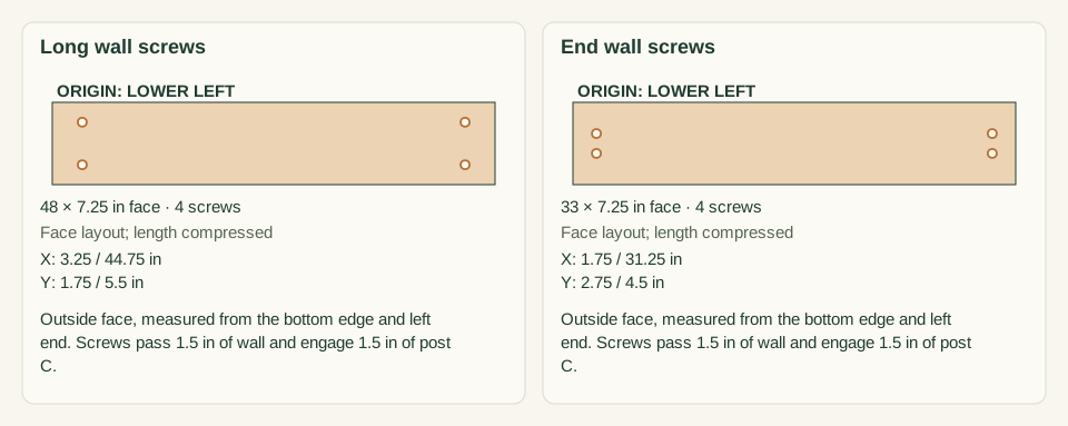
Mark the outside face of each L from its bottom edge. Draw lines 3.25 inches in from each end. Mark points on each line at 1.75 and 5.5 inches above the bottom edge. On each E, draw lines 1.75 inches from each end and mark points at 2.75 and 4.5 inches above the bottom edge.
Close-up · Whole model shows the complete part
Loading the 3D view…
Drag to turn. Pinch or use + / − to zoom. The written step covers workholding and tool use.
Scroll or swipe the enlarged drawing to read its dimensions. Choose Fit to see the whole drawing again.
The long-wall and end-wall marks sit at different heights so the screws miss each other inside the post.
Check: Each wall shows four marks, and the L and E heights are staggered by at least 1 inch.
- 07
Dry-fit and square the walls
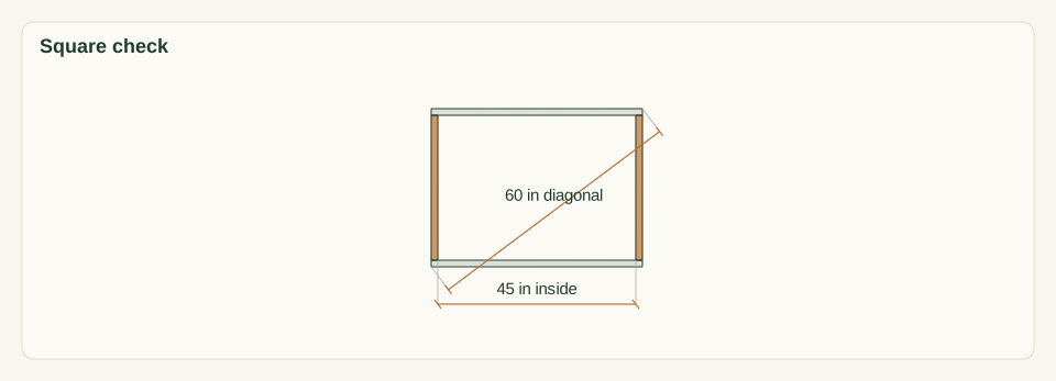
Lay all four walls bottom edge down on a flat surface with the outside faces out. Fit both E walls between the ends of the L walls with the ends flush. Clamp each corner. Measure 48 inches outside along L, 36 inches outside along E and 45 × 33 inches inside. Measure both outside diagonals.
Close-up · Whole model shows the complete part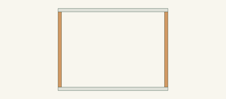
Loading the 3D view…
Drag to turn. Pinch or use + / − to zoom. The written step covers workholding and tool use.
Scroll or swipe the enlarged drawing to read its dimensions. Choose Fit to see the whole drawing again.
The end walls fit between the long walls. Equal diagonals confirm the frame is square.
Check: Both diagonals read 60 inches within 1/8 inch, and the frame lies flat without forcing.
- 08
Fit posts and drive the 16 corner screws
Set one C post in each inside corner, flush top and bottom and tight to both walls. Clamp each wall to its post. Trial the screw in scrap. At each mark, drill a clearance hole through the wall only and a pilot into the post as the screw maker directs. Drive two #10 × 3-inch screws per wall face. Recheck the 60-inch diagonals after each corner.
Close-up · Whole model shows the complete part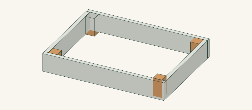
Loading the 3D view…
Drag to turn. Pinch or use + / − to zoom. The written step covers workholding and tool use.
Scroll or swipe the enlarged drawing to read its dimensions. Choose Fit to see the whole drawing again.
Every post takes two screws through each adjoining wall: a clearance hole in the wall and a pilot in the post.
Check: All 16 screws are seated flush, no post has split and the diagonals still read 60 inches.
- 09
Inspect the corners while visible
Release all clamps. Inspect each C post and wall end for splits, stripped holes, projecting screw points and gaps at the joints. Ease the hand-contact rim edges and check for splinters with a cloth. Record the outside size of 48 × 36 inches and both diagonals before the frame moves to the site.
Close-up · Whole model shows the complete part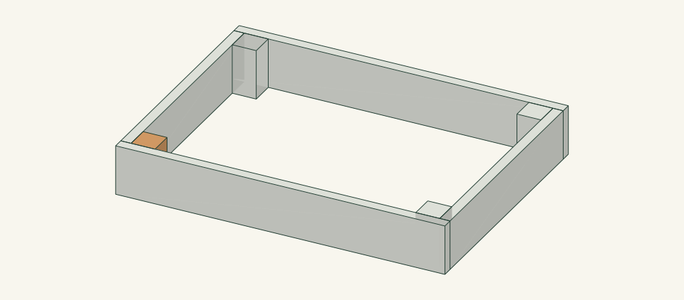
Loading the 3D view…
Drag to turn. Pinch or use + / − to zoom. The written step covers workholding and tool use.
Scroll or swipe the enlarged drawing to read its dimensions. Choose Fit to see the whole drawing again.
Check each corner for splits, gaps and screw points while it is still exposed. Repeat at all four corners.
Check: Every corner is closed and sound, and the record shows 48 × 36 inches outside.
- 10
Cut the level bench
Lay out a 56 × 40-inch bench. It extends 4 inches beyond each end of the 48-inch frame and 4 inches behind the 36-inch depth. Use the ground under the front downhill edge as the level datum. Remove soil by hand from the uphill side down to that datum. Never cut deeper than 2 inches, and never add fill. Carry spoil away from the bench.
Close-up · Whole model shows the complete part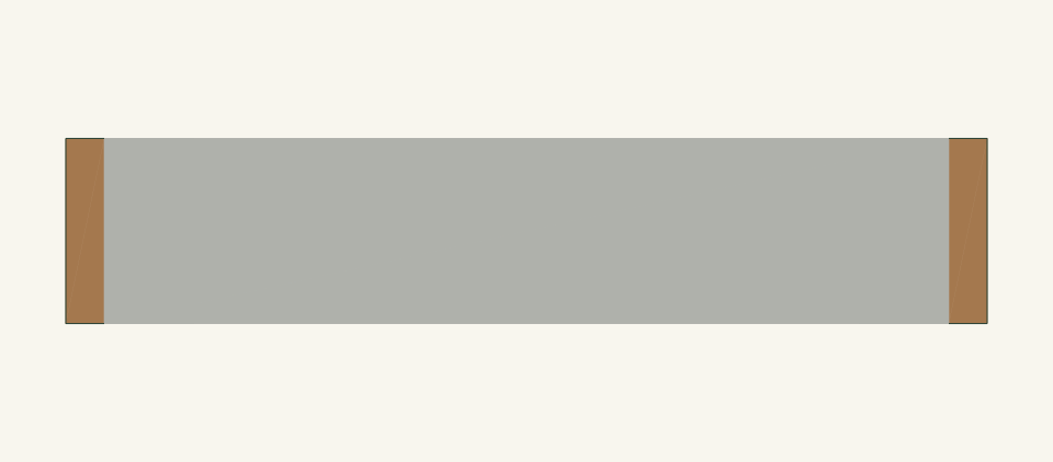
Loading the 3D view…
Drag to turn. Pinch or use + / − to zoom. The written step covers workholding and tool use.
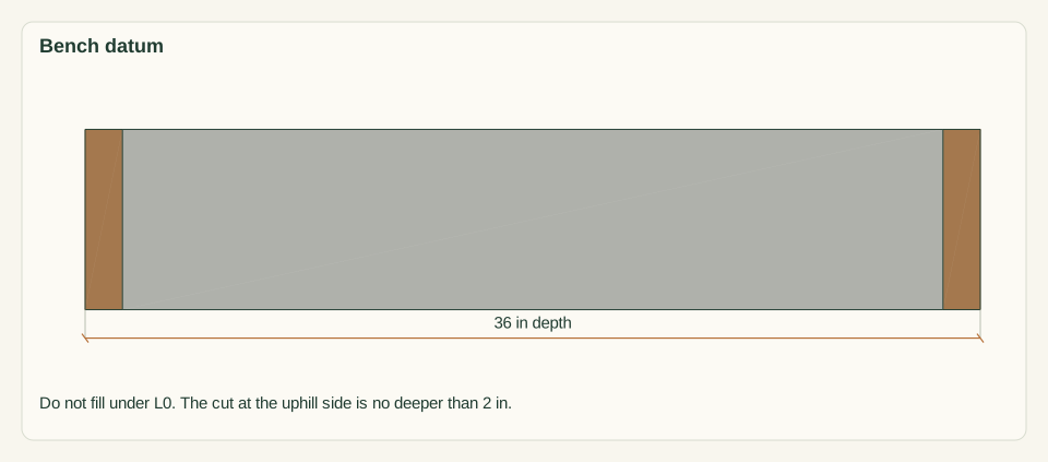
Scroll or swipe the enlarged drawing to read its dimensions. Choose Fit to see the whole drawing again.
Planning reference. The bench is cut down to the grade under the front wall. The earthwork is shown in the feature section, not the model.
Check: The bench is level within 1/8 inch both ways, and the uphill cut face is no taller than 2 inches.
- 11
Place and level the empty frame
With a helper, carry the empty frame supported under both L walls. Set the downhill wall L0 along the front edge of the bench with 4 inches of bench beyond each end. Check level along L0, along L1 and across both E walls. Look for gaps under all four walls. Do not shim with scraps or loose soil.
Close-up · Whole model shows the complete part
Loading the 3D view…
Drag to turn. Pinch or use + / − to zoom. The written step covers workholding and tool use.
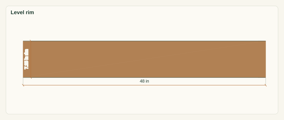
Scroll or swipe the enlarged drawing to read its dimensions. Choose Fit to see the whole drawing again.
Check the rim level in both directions and confirm full bearing under each wall.
Check: All four walls bear fully on cut soil, and the rim is level within 1/8 inch end to end and front to back.
- 12
Test runoff before filling
Run a low-flow hose on the grade above the uphill cut face for several minutes. Watch the water cross the 4-inch strip behind L1, move to the bench ends and pass around the frame. Check for ponding against L1, scour at the cut face or wash-out under L0. Then mulch the strip and the cut face.
Close-up · Whole model shows the complete part
Loading the 3D view…
Drag to turn. Pinch or use + / − to zoom. The written step covers workholding and tool use.
Scroll or swipe the enlarged drawing to read its dimensions. Choose Fit to see the whole drawing again.
Water from uphill must cross the strip behind the back wall and pass around the bed ends.
Check: Water clears the strip without ponding against the back wall or undercutting any wall.
- 13
Fill to the line in passes
Mark a line 6.25 inches above the bench on the inside face of every wall. Add about 5.2 cubic feet of the selected growing medium in thin passes around the whole bed. Do not dump against L0 first. Watch the front wall and corners during each pass. Do not stand on the rim.
Close-up · Whole model shows the complete part
Loading the 3D view…
Drag to turn. Pinch or use + / − to zoom. The written step covers workholding and tool use.
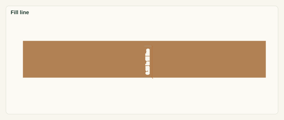
Scroll or swipe the enlarged drawing to read its dimensions. Choose Fit to see the whole drawing again.
The fill line leaves 1 inch of freeboard below the rim.
Check: The fill reaches the 6.25-inch line evenly with 1 inch of freeboard, and no wall has moved.
- 14
Water and make the final inspection
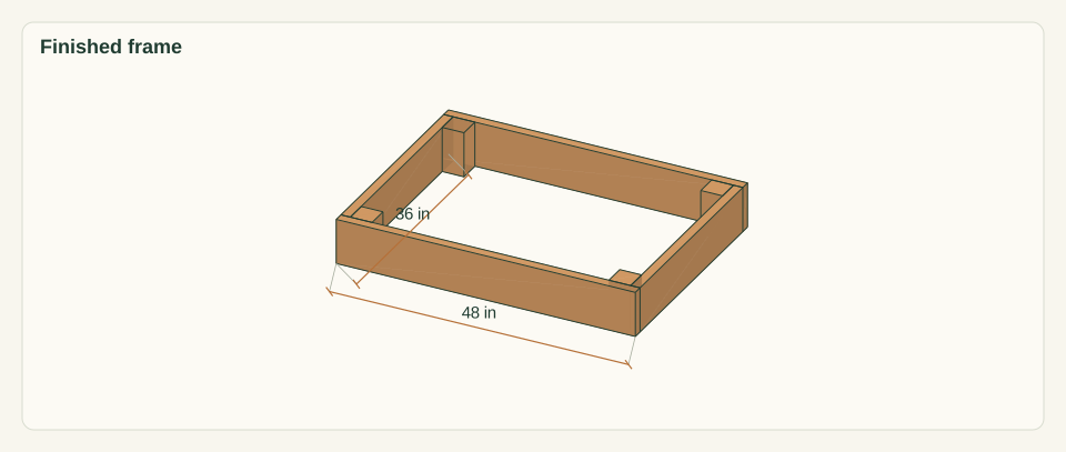
Water gently and watch drainage and settlement. Recheck rim level, the 60-inch diagonals, every corner and the gap between L1 and the cut face. Confirm that the mulch still covers the strip and cut face. Top up settled medium only to the 6.25-inch line. Record any change before planting.
Close-up · Whole model shows the complete partLoading the 3D view…
Drag to turn. Pinch or use + / − to zoom. The written step covers workholding and tool use.
Scroll or swipe the enlarged drawing to read its dimensions. Choose Fit to see the whole drawing again.
Final overview of the level frame on the bench, ready for planting.
Check: The rim is still level, the corners are closed, the strip drains and nothing has washed below L0.


05 / Keep it sound
Care
After the build
- Fill only after the runoff test passes and the mulch covers the 4-in strip and the cut face.
- Plant to crop-specific spacing and reach. Keep pots, tools and people off the rim.
Check it each season
- After heavy rain, check the strip behind L1 for ponding and debris, and check under L0 for wash-out. Clear debris and renew mulch.
- Each season, check rim level, corners and screw heads. Replace a split post or a softened wall rather than adding screws or trim beside the damage.
If something looks wrong
- Water ponds behind the back wall
- Stop watering, clear the strip and rake it to drain to both ends. Do not cut a channel through the bed.
- Soil washes out under the front wall
- Unload the affected area and stop use. Refer the site, and do not pack loose fill under the wall.
- Frame rocks or is out of level after placing
- Lift it off and recut the bench to undisturbed soil. Never shim with wood scraps or loose soil.
- A corner opens or the front wall bows while filling
- Stop filling and remove soil from that side. Inspect the post and screws before any repair.
- The cut face slumps toward the bed
- Remove the slumped soil from the strip and re-mulch. Refer the site if slumping recurs.
Keep exploring