Wooden raised beds · Guide 39
Build a Lined-Floor Cedar Raised Bed for Paving
A 50 × 26.5-inch cedar bed with a slatted floor, a permeable fabric liner and raised runners that holds growing media on paving while water drains out.
01 / See the shape
View the project
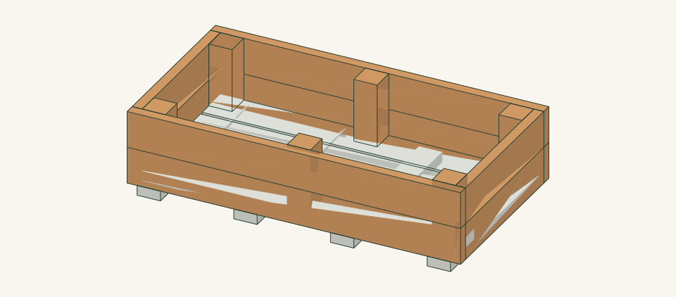
Loading the 3D view…
Drag to turn. Pinch or use + / − to zoom. The written step covers workholding and tool use.

Scroll or swipe the enlarged drawing to read its dimensions. Choose Fit to see the whole drawing again.
Every joint is still visible before the liner covers the inside faces.
02 / Plan your build
Before you start
A bed on paving cannot drain into soil below, so this design gives the water a planned path. The media sits on a fabric liner laid over four floor boards. The liner is water-permeable geotextile, not a waterproof membrane. Water passes through the fabric and the three 0.5-inch floor gaps, then runs out over the paving through the 1.5-inch space between four runners. The floor rests directly on the runners, and the runners rest on the paving, so the media weight does not hang from wall screws. The main failure is trapped water. A sealed plastic liner, blocked floor gaps, or runners set across the paving fall will hold water in the media and against the wood. The second failure is unreviewed bearing: the paving, slab and ground beneath must carry the full saturated bed, and this guide does not rate that.
Where it goes
Sound, continuous paving with a fall that carries water away from buildings, doorways and unchecked drains, and room to reach from both long sides. Not on a deck, roof, balcony, stair, cracked or loose pavers, a utility cover, or any surface over a void.
Footprint: 50 × 26.5 in on sound paving, plus at least 24 in of clear working access on every side and a clear surface path for drained water leaving from under both long walls
What to expect
Measure accurately, make supported square cuts, drill clamped pilot holes and move long boards with a helper. Plan 7–9 hours for two people including cutting, assembly and the empty water test, plus separate time to fill and settle the media.
A planning estimate for the hands-on work, once the materials are bought and the tools are set up. It has not been timed on a finished build.
Check the spot
- Confirm the paving is continuous and uncracked, is not over a void, and is not a deck, roof, balcony, stair or utility cover.
- Confirm water poured on the footprint flows to a safe outlet away from buildings, doorways and unchecked drains.
- Confirm 24 inches of working access on all sides and reach from both long sides.
- Confirm with a qualified reviewer that the paving and the ground beneath can carry the saturated filled bed; this guide does not.
Stop and check first if…
- Stop if the paving capacity has not been confirmed, or the paving is cracked, loose, hollow-sounding or over a void.
- Stop if water poured on the footprint ponds or runs toward a building.
- Stop if a runner does not bear fully or the floor rocks; do not pack it with loose shims.
- Stop if a part splits, a screw strips, or the selected screw instructions cannot be met in these sections.
- Stop if water stands on the liner during the empty test.
- Stop filling if a wall bows, a joint opens or a corner moves; unload before repair.
Work safely
- Follow the actual saw and drill instructions and keep guards in place. Clamp short post pieces to the bench; never hold a 9.5-inch post freehand beside a blade.
- Clamp each joint before drilling so a caught bit cannot spin a board. Keep fingers away from closing clamps.
- Move the empty frame with two people supporting both long walls. Do not move the bed once media is in it.
- Wet paving is slippery; keep the hose test water off walking routes.
Budget
We have not put a price on this one yet. Lumber and hardware prices change by store and season, so price the list under What you need at your local supplier before you buy.
03 / Gather and cut
What you need
L — Long wall board
4 pieces
Untreated cedar 2 × 6; actual 1.5 × 5.5 in. Four 2 × 6 × 8-ft boards shared with E: 50 + 23.5 + two 0.125-in kerfs + 1.0-in end trim = 74.75 in from each 96-in board, leaving a 21.25-in spare offcut.
Reject boards with splits within 4 in of a cut end, loose knots at a screw position, or twist that stops the board lying flat. Mark the bottom edge on every board.
E — End wall board
4 pieces
Untreated cedar 2 × 6; actual 1.5 × 5.5 in. Cut from the same four 2 × 6 × 8-ft boards as L; one E per board.
E fits between the L boards. Check the 23.5-in length against the measured inside depth after the floor boards are laid.
F — Floor board
4 pieces
Untreated cedar 2 × 6; actual 1.5 × 5.5 in. Two 2 × 6 × 8-ft boards: 2 × 47 + two 0.125-in kerfs + 1.0-in end trim = 95.25 in from each 96-in board. There is no spare; buy one extra board if any end is defective.
Floor boards carry the media weight between runners. Reject any board with a through-split, decay or a large knot within the 11-in clear span.
R — Runner
4 pieces
Untreated cedar 2 × 4 laid flat; actual 1.5 × 3.5 in. Two 2 × 4 × 8-ft boards: three runners from one board (3 × 26.5 + three 0.125-in kerfs + 1.0-in trim = 80.875 in) and one from the second.
Runners sit on wet paving and will deteriorate first. A reviewer must confirm the species is suitable for this exposure. Choose the flattest stock so all four bear evenly.
P — Post
6 pieces
Untreated cedar 4 × 4; actual 3.5 × 3.5 in. One 4 × 4 × 8-ft: 6 × 9.5 + six 0.125-in kerfs + 1.0-in trim = 58.75 in.
Cut both ends square so each post stands on the floor without rocking. Reject posts with end checks longer than 1 in.
N — Bottom liner
1 piece
Nonwoven, water-permeable geotextile fabric. Not a waterproof membrane, not plastic sheet. One piece from a roll at least 38 in wide. Floor 47 × 23.5 plus a 6-in turn-up on every side = 59 × 35.5, plus fitting margin = 62 × 38 in.
Confirm from the product data that the fabric passes water and is suitable for contact with growing media. Do not substitute a sealed liner.
Wall screws
46 items
#10 × 3 in stainless steel exterior wood screws, type 305 or 316, for wet soil-contact exposure Purchase at least 46; keep spares separate from the installed count.
40 fix wall boards to posts and 6 fix the lower long walls into the front and back floor board edges. Follow the product pilot, clearance and edge-distance instructions. No connection capacity is inferred.
Floor screws
32 items
#10 × 2.5 in stainless steel exterior wood screws, type 305 or 316 Purchase at least 32; keep spares separate from the installed count.
Two per floor board at each of four runners. The tip stops 0.5 in above the paving. No connection capacity is inferred.
Liner staples
28 items
Stainless steel staples, 3/8 in leg Purchase at least 28 plus spares for misfires.
Nine along each long side and five along each end on a line 5 in above the floor top.
Cut list
| Piece | How many | Cut length | Note |
|---|---|---|---|
| L — Long wall board | 4 | 50 × 5.5 × 1.5 in | Finished length × width × thickness; square ends unless the detail says otherwise. |
| E — End wall board | 4 | 23.5 × 5.5 × 1.5 in | Finished length × width × thickness; square ends unless the detail says otherwise. |
| F — Floor board | 4 | 47 × 5.5 × 1.5 in | Finished length × width × thickness; square ends unless the detail says otherwise. |
| R — Runner | 4 | 26.5 × 3.5 × 1.5 in | Finished length × width × thickness; square ends unless the detail says otherwise. |
| P — Post | 6 | 9.5 × 3.5 × 3.5 in | Finished length × width × thickness; square ends unless the detail says otherwise. |
Tools
- Tape measure, combination square, chalk line and pencil
- Straightedge and 24-inch or longer level
- Suitable guarded saw with supported stock and clamps
- Drill/driver with bits and countersink matched to the selected screws
- Four bar clamps long enough to span 26.5 inches
- Three 0.5-inch spacers, a stapler for the selected staples and sharp scissors
- Garden hose and a bucket for drainage checks
Protective gear
- Eye protection during cutting, drilling and stapling
- Hearing protection and dust collection suited to the actual saw
- Closed footwear and gloves for handling boards; remove gloves near rotating cutters
04 / Put it together
Build steps
- 01
Confirm the paving and drainage path
Mark the 50 × 26.5-inch footprint on the paving with chalk. Pour a bucket of water on the marked area and watch which way it runs. Plan the R runners to run front to back in the same direction as that flow, so water leaves from under both long L walls. Confirm the paving is continuous, uncracked and not a deck, roof or utility cover.
Close-up · Whole model shows the complete part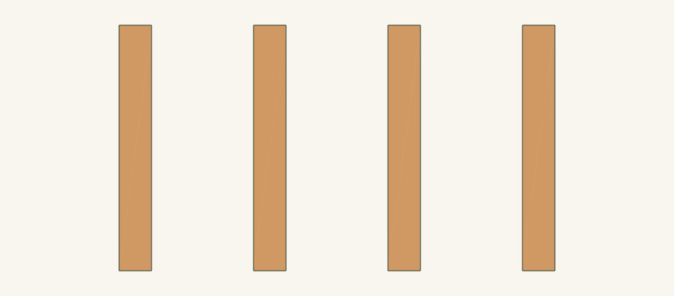
Loading the 3D view…
Drag to turn. Pinch or use + / − to zoom. The written step covers workholding and tool use.
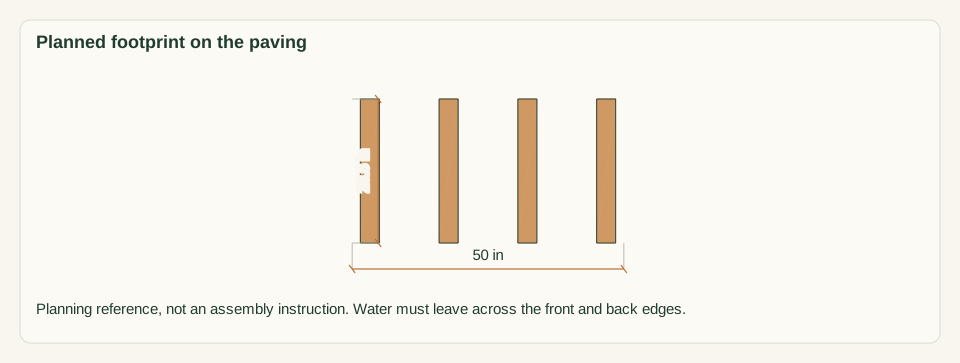
Scroll or swipe the enlarged drawing to read its dimensions. Choose Fit to see the whole drawing again.
Planning reference only: the runners will run front to back, following the paving fall.
Check: Water runs off the footprint toward a safe outlet, away from buildings, with no pooling inside the chalk lines.
- 02
Measure the stock sections
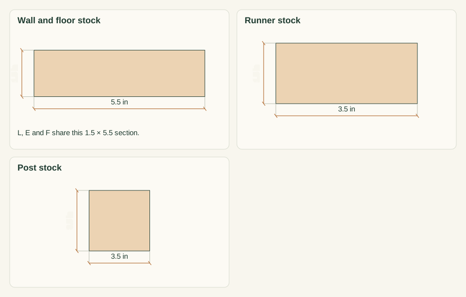
Measure each 2 × 6 at both ends and the middle; this plan needs 1.5 × 5.5 inches for L, E and F. Check the 2 × 4 runner stock at 1.5 × 3.5 inches and the 4 × 4 post stock at 3.5 × 3.5 inches. Sight each board for twist and record usable lengths after defective ends.
Close-up · Whole model shows the complete part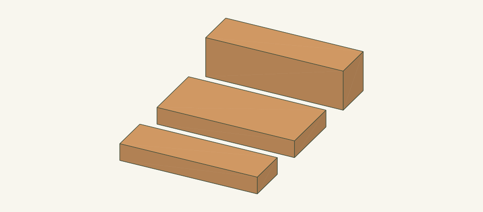
Loading the 3D view…
Drag to turn. Pinch or use + / − to zoom. The written step covers workholding and tool use.
Scroll or swipe the enlarged drawing to read its dimensions. Choose Fit to see the whole drawing again.
Compare the measured sections with the actual sizes the plan depends on.
Check: All sections match the plan within 1/16 inch; different stock stops the build until the design is reconciled.
- 03
Cut the wall boards
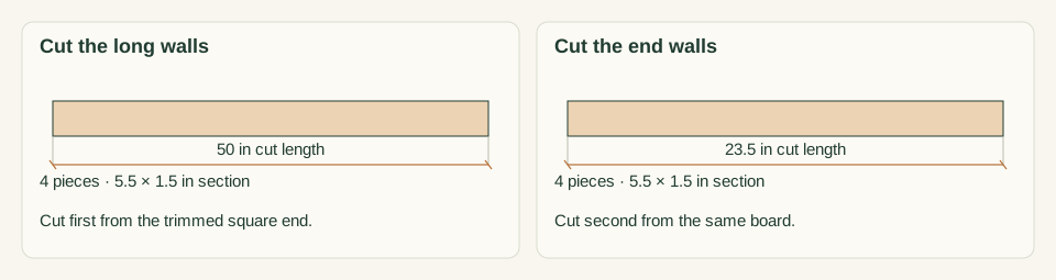
Trim 0.5 inch from one factory end of each of four 2 × 6 boards. From that square end cut one 50-inch L, then one 23.5-inch E, keeping the kerf on the waste side. Clamp and support both sides of each cut. Label every board on its bottom edge.
Close-up · Whole model shows the complete part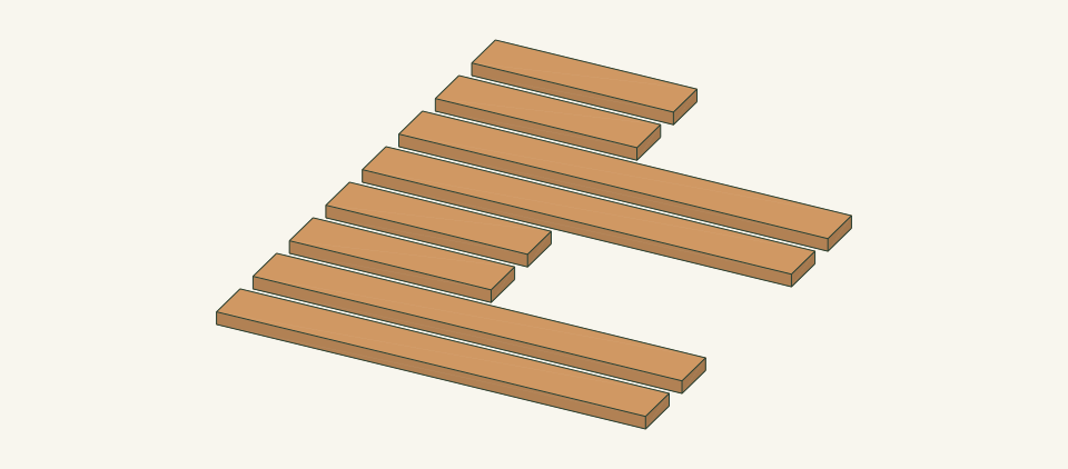
Loading the 3D view…
Drag to turn. Pinch or use + / − to zoom. The written step covers workholding and tool use.
Scroll or swipe the enlarged drawing to read its dimensions. Choose Fit to see the whole drawing again.
One long wall and one end wall come from each of four boards.
Check: Four L at 50 inches and four E at 23.5 inches match their pairs face to face.
- 04
Cut the floor boards runners and posts
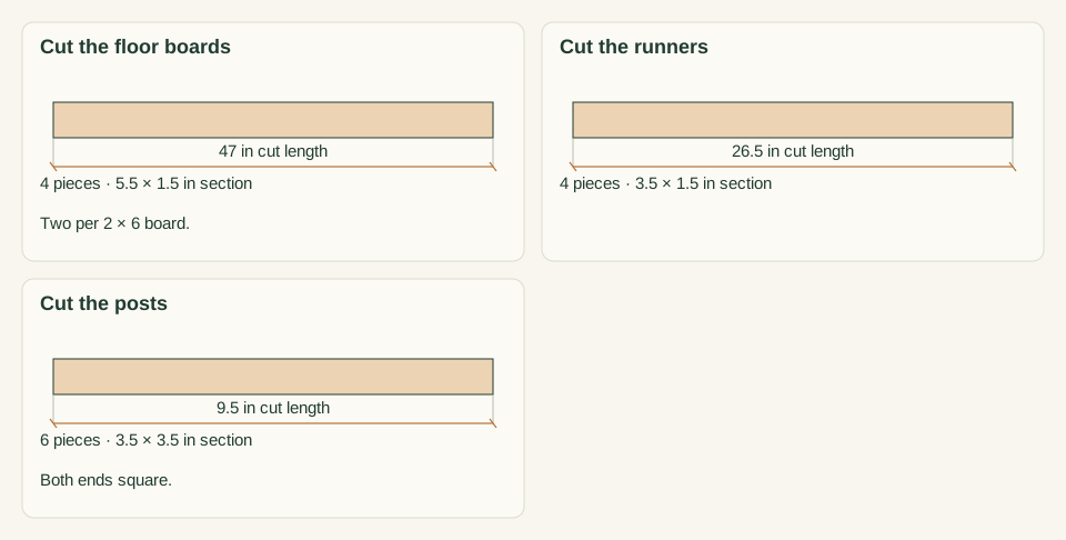
Cut four 47-inch F boards, two from each of the remaining 2 × 6 boards after a 0.5-inch end trim. Cut four 26.5-inch R runners from the 2 × 4 stock. Cut six 9.5-inch P posts from the 4 × 4, with both ends square.
Close-up · Whole model shows the complete part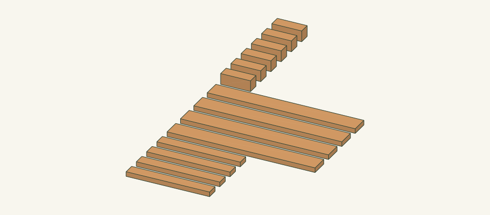
Loading the 3D view…
Drag to turn. Pinch or use + / − to zoom. The written step covers workholding and tool use.
Scroll or swipe the enlarged drawing to read its dimensions. Choose Fit to see the whole drawing again.
Floor boards, runners and posts are cut from separate stock.
Check: Four F, four R and six P are cut; each post stands on a flat surface without rocking.
- 05
Mark screw positions on every face
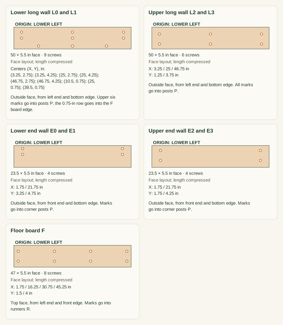
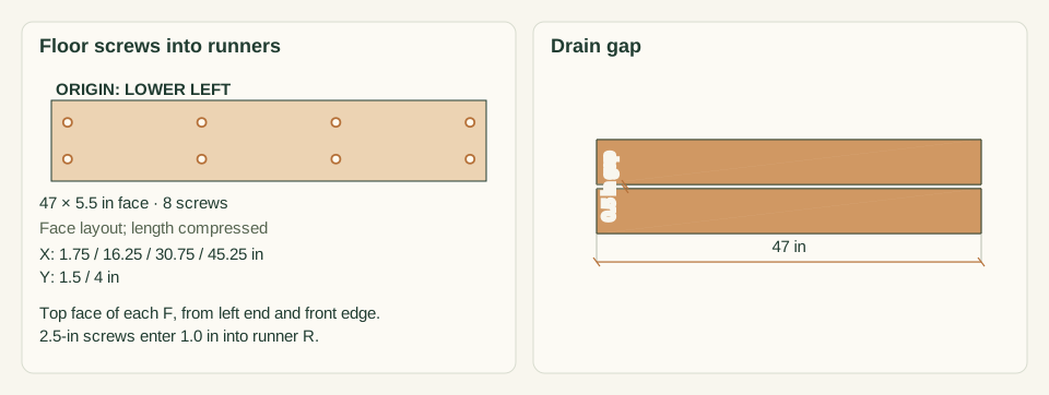
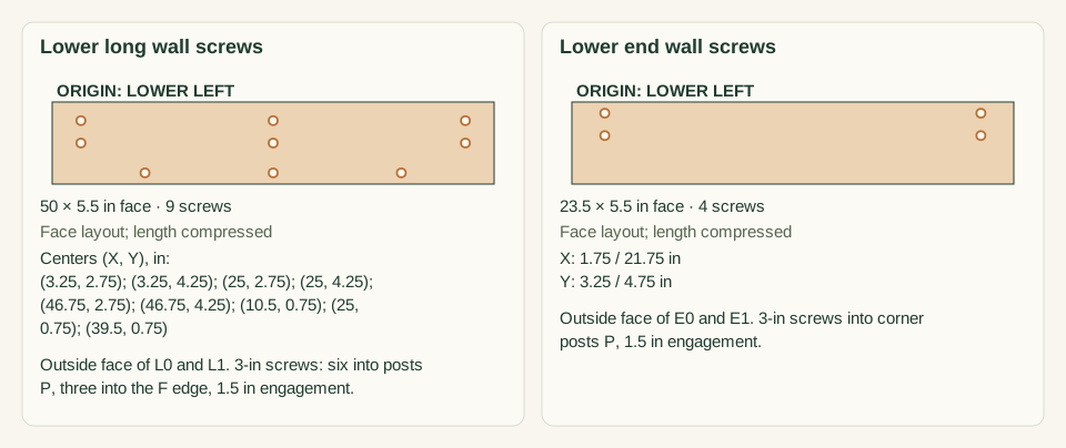
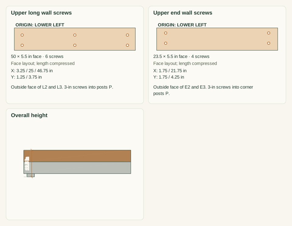
Mark each pattern on the outside face measured from the left end and the bottom edge. F boards get 8 marks at 1.75, 16.25, 30.75 and 45.25 inches along, 1.5 and 4.0 inches across. Lower L boards get 9 marks, upper L boards 6, and every E board 4, at the heights in the connection schedule. All patterns are symmetric end to end.
Close-up · Whole model shows the complete part
Loading the 3D view…
Drag to turn. Pinch or use + / − to zoom. The written step covers workholding and tool use.
Scroll or swipe the enlarged drawing to read its dimensions. Choose Fit to see the whole drawing again.
Each board type has its own mark pattern; lower and upper courses differ.
Check: Mark counts are 32 on F, 18 on lower L, 12 on upper L and 16 on E.
- 06
Set the runners on the paving
Sweep the footprint clean. Lay the four R runners flat, running front to back, at 1.5, 16, 30.5 and 45 inches from the chalked left edge. Each runner spans the full 26.5-inch depth. Keep 11 inches clear between neighbouring runners and align their front ends on a straightedge.
Close-up · Whole model shows the complete part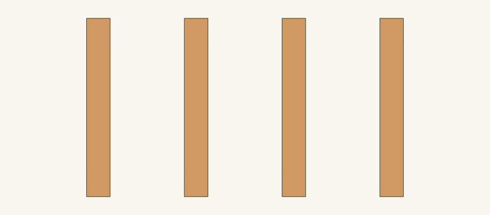
Loading the 3D view…
Drag to turn. Pinch or use + / − to zoom. The written step covers workholding and tool use.

Scroll or swipe the enlarged drawing to read its dimensions. Choose Fit to see the whole drawing again.
Equal clear spaces keep the floor spans short and leave drain channels open.
Check: All four runners bear fully on the paving without twisting, and the existing drainage fall remains open; do not use loose shims.
- 07
Fasten the floor boards to the runners
Lay F0 to F3 across the runners with their left ends 1.5 inches in from the chalked left edge. Space the boards with 0.5-inch spacers, starting 1.5 inches back from the chalked front edge. Drill the product-specified pilots at the marks and drive two 2.5-inch screws per board at each runner, 32 in total.
Close-up · Whole model shows the complete part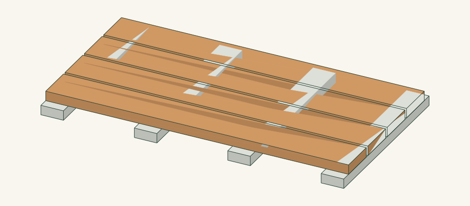
Loading the 3D view…
Drag to turn. Pinch or use + / − to zoom. The written step covers workholding and tool use.
Scroll or swipe the enlarged drawing to read its dimensions. Choose Fit to see the whole drawing again.
Floor boards rest on the runners and leave three drain gaps.
Check: Floor is 47 × 23.5 inches with three open 0.5-inch gaps and no screw point showing below a runner.
- 08
Dry-fit the lower walls and posts
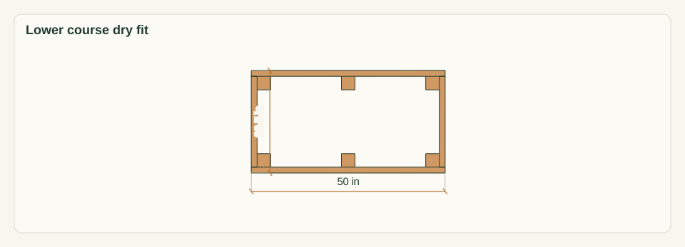
Stand lower L0 and L1 on the runner ends against the front and back floor edges, flush with the runner ends. Fit lower E0 and E1 between them against the floor ends. Stand corner posts P0 to P3 on the floor in each inside corner and P4 and P5 centred on the long walls at 23.25 inches from the left end. Clamp each wall board to its posts.
Close-up · Whole model shows the complete part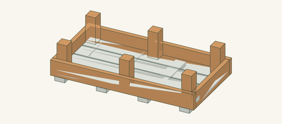
Loading the 3D view…
Drag to turn. Pinch or use + / − to zoom. The written step covers workholding and tool use.
Scroll or swipe the enlarged drawing to read its dimensions. Choose Fit to see the whole drawing again.
Long walls run through; end walls fit between; posts stand on the floor.
Check: Outside measures 50 × 26.5 inches and both outside diagonals are about 56.59 inches, within 1/8 inch of each other.
- 09
Screw the lower walls to posts and floor
With the clamps on, drill clearance holes through L0, L1, E0 and E1 and product-specified pilots into the posts and floor edges. Drive 12 screws through the lower L boards into posts, 6 into the F board edges at 0.75 inch high, and 8 through the lower E boards into the corner posts. All are 3-inch screws.
Close-up · Whole model shows the complete part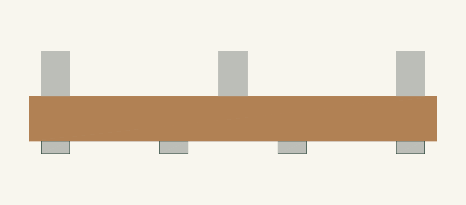
Loading the 3D view…
Drag to turn. Pinch or use + / − to zoom. The written step covers workholding and tool use.
Scroll or swipe the enlarged drawing to read its dimensions. Choose Fit to see the whole drawing again.
The lowest row ties each long wall to the floor edge behind it.
Check: 26 screws are seated flush with no split post, floor edge or wall end.
- 10
Fit and screw the upper walls
Set upper L2 and L3 on the lower L boards and upper E2 and E3 on the lower E boards. Keep their top edges flush with the post tops at 12.5 inches. Clamp, drill and drive 12 screws through the upper L boards and 8 through the upper E boards into the posts, all 3-inch.
Close-up · Whole model shows the complete part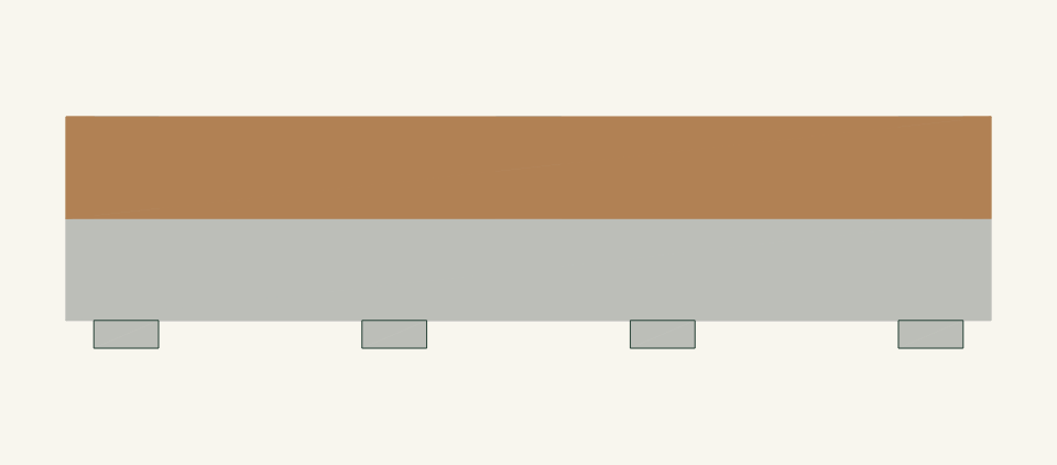
Loading the 3D view…
Drag to turn. Pinch or use + / − to zoom. The written step covers workholding and tool use.
Scroll or swipe the enlarged drawing to read its dimensions. Choose Fit to see the whole drawing again.
Upper screws sit lower than the lower-course pattern to keep clear of the post tops.
Check: Height is 12.5 inches at every corner and the course seam is closed along all four walls.
- 11
Inspect the frame before lining
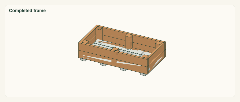
Release all clamps. Recheck the 50 × 26.5-inch outside size and both diagonals. Inspect every post, wall end and floor board for splits, stripped holes and projecting points. Ease the top edges for hand contact. Confirm all 78 screws are present: 32 floor, 6 floor-edge and 40 post.
Close-up · Whole model shows the complete partLoading the 3D view…
Drag to turn. Pinch or use + / − to zoom. The written step covers workholding and tool use.
Scroll or swipe the enlarged drawing to read its dimensions. Choose Fit to see the whole drawing again.
Every joint is still visible before the liner covers the inside faces.
Check: The frame stays square without clamps and every joint is sound while still visible.
- 12
Fit and staple the fabric liner
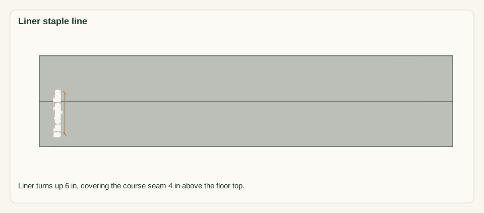
Lay the 62 × 38-inch N liner over the floor and press it into the corners. Slit it at each post and fold it up the post faces. Turn it 6 inches up every wall so it covers the course seam. Staple on a line 5 inches above the floor top, no more than 6 inches apart, 9 per long side and 5 per end. Trim the excess above the staple line to 1 inch.
Close-up · Whole model shows the complete part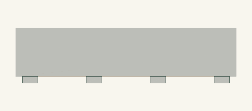
Loading the 3D view…
Drag to turn. Pinch or use + / − to zoom. The written step covers workholding and tool use.
Scroll or swipe the enlarged drawing to read its dimensions. Choose Fit to see the whole drawing again.
The fabric liner is not modeled; the dimension shows its staple line above the floor.
Check: 28 staples hold the liner flat on the floor, with no fold bridging a floor gap and no tear.
- 13
Water test the empty lined bed
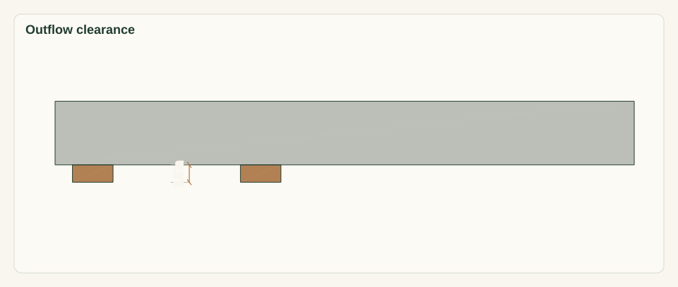
Run a hose gently onto the liner for one minute. Watch from the long sides as water leaves through the floor gaps and runs out under L0 and L1 across the paving. Wait 15 minutes and look inside for standing water.
Close-up · Whole model shows the complete part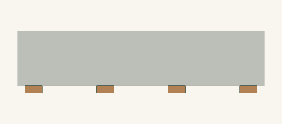
Loading the 3D view…
Drag to turn. Pinch or use + / − to zoom. The written step covers workholding and tool use.
Scroll or swipe the enlarged drawing to read its dimensions. Choose Fit to see the whole drawing again.
Water exits through the 1.5-inch space under the long walls between runners.
Check: No water stands on the liner and the outflow reaches the planned safe path without wetting a building wall.
- 14
Fill in passes to the fill line
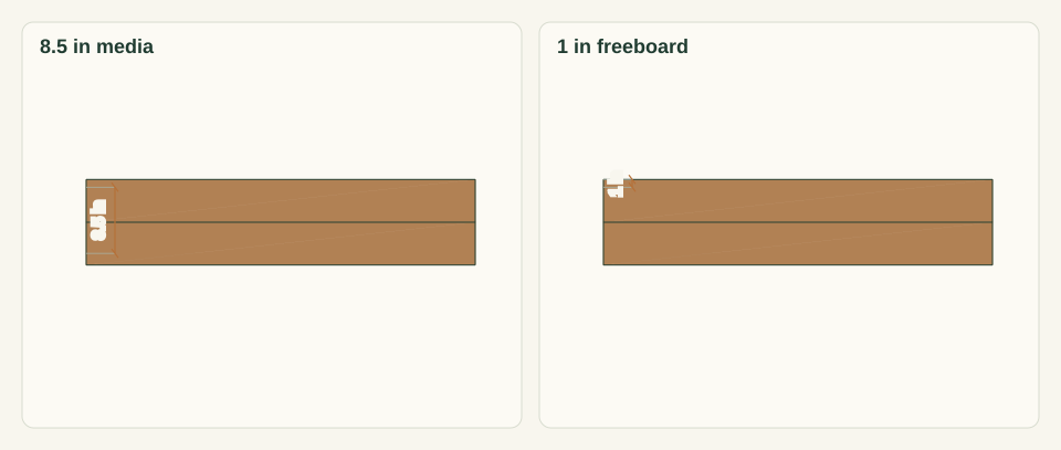
Mark the fill line 11.5 inches above the paving, 8.5 inches above the floor top, on the inside of every wall. Add the selected growing media in thin passes around the bed rather than dumping it against one wall. Water lightly and add media only to the marked line. Leave the 1-inch freeboard below the 12.5-inch rim.
Close-up · Whole model shows the complete part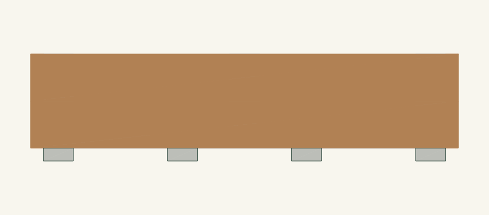
Loading the 3D view…
Drag to turn. Pinch or use + / − to zoom. The written step covers workholding and tool use.
Scroll or swipe the enlarged drawing to read its dimensions. Choose Fit to see the whole drawing again.
Media fills to the marked line, leaving freeboard below the rim.
Check: Media is level at the fill line and no wall, post or corner has moved.
- 15
Make the first inspection
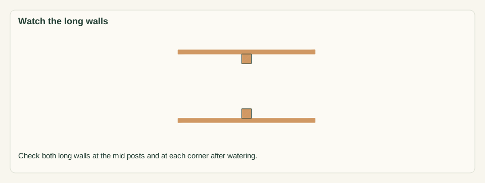
After the first thorough watering, check outflow under both long walls and look for staining or pooling on the paving. Check all four walls for bowing at the mid posts P4 and P5 and at each corner. Probe the media surface near the floor gaps for soft wet spots. Repeat after the first week.
Close-up · Whole model shows the complete part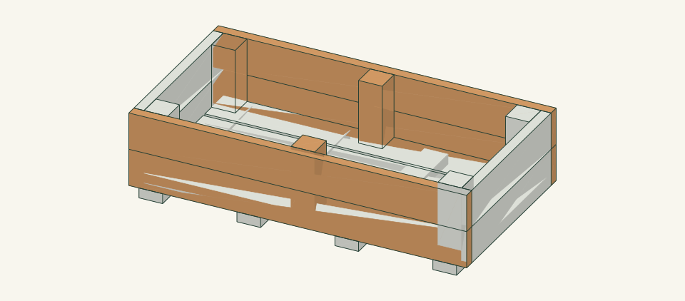
Loading the 3D view…
Drag to turn. Pinch or use + / − to zoom. The written step covers workholding and tool use.
Scroll or swipe the enlarged drawing to read its dimensions. Choose Fit to see the whole drawing again.
Mid posts and long walls are where bowing would show first.
Check: Water drains within the time seen in the empty test and no wall has bowed or opened at a joint.


05 / Keep it sound
Care
After the build
- Fill only after the empty water test passes. Keep media at the 11.5-inch fill line and never above the rim.
- Use crops suited to 8.5 inches of media and water to the media supplier's guidance. Keep pots, tools and people off the walls.
Check it each season
- Each season, check outflow under both long walls after watering and clear debris blocking the gap between the runners.
- Inspect runners, posts and wall bases for softening. Unload the bed before replacing any part; replace a decayed runner or split board rather than adding screws beside it.
- Check that the liner has not torn or slipped down a wall. Expect cedar tannin staining on the paving.
If something looks wrong
- Water stands on top of the media
- Stop watering. Check the outflow path under the long walls and look for silt clogging the liner; replace the liner if it is sealed with fines.
- No water leaves from under the bed
- Check that the runners run with the paving fall and that debris has not dammed the gaps between them.
- Media leaks through a floor gap
- Empty the affected area, find the liner tear or slipped edge, and fit a new liner piece with a full turn-up.
- A long wall bows near the middle
- Stop and lower the media level. Inspect the screws at P4 or P5 and the floor-edge screws, and refer the wall for review before refilling.
- The bed rocks on the paving
- Empty it. Find the high point and check runner flatness; relocate rather than shimming.
- Paving shows cracks or settlement after filling
- Stop using the bed, empty it, and refer the paving to a qualified reviewer.
Keep exploring